To avoid these ads, REGISTER NOW!

advice from some welders

d_rock

Well-known member
Joined
Apr 14, 2012
Messages
192
Location
Denver
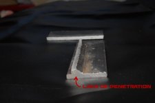
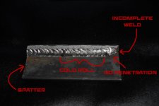
So i've been working as a full time welder/fabricator for almost a year now. Never went to school for it or had any formal training besides high school shop. Decided i'd perform a "break test" on myself after work today and I FAILED it. :headscrat SOOOOOOOOO, looking for some advice. actually I did a few more and failed all of them using different settings/techniques. The actual weld itself held, but the plate broke in half right above the weld. Anyway, a picture is worth a thousand words so give it to me!!

Miller 212
21.5 volts
290 wire speed
co2
(factory settings on the door)


To avoid these ads, REGISTER NOW!

zkling

Well-known member
Joined
Jan 23, 2007
Messages
16,939
Kinda of hard to tell from the pics. If you want a better analysis. weld a T joint just like you did, cut it in half then etch the weld with some type of acid. Vinegar would work if left in long enough. Phosphoric or nitric would be better. This will show you where the weld penetration ends and the base metal begins.

For a bend test try welding ~2" wide strips and bending them 180°.

As for what you did. I looks like a pretty decent weld. As you said it broke in the base metal. How far did you bend it for it to break like that. Most weldable steels wouldn't break off like that*. If anything your weld bead looks a bit cold, as the toes (edges) of the weld don't flow into the base metal. Additionally watch the end of your beads for cracks. You don't want the end to taper off, it should be of the same height and rounded to prevent cracking, which is present in the right hand side of your weld bead.

*That plate fractured like a high carbon or brittle steel would, which leads me to believe that it got too hot during welding, or you were using some goofy steel.

One last thing, try cleaning off the scale with a flap wheel or the like before welding. I understand you are using mig w/ Co2, which can withstand dirty conditions, but can also hide defects.

Did you weave the mig gun when you welded this? Also what wire size and base material thickness were you using?
 
Last edited:
OP
D

d_rock

Well-known member
Joined
Apr 14, 2012
Messages
192
Location
Denver
It broke off right about 160 i'd say. I didn't weave it, i used a lower case e "technique" for lack of a better way to put it. its .035 wire on 1/4 plate.
 

kkroger

Well-known member
Joined
Apr 21, 2013
Messages
1,143
What exactly is the steel? Shear Drop or do you know what you got?
That brittleness is strange but I can't fault your weld, it appears to have done it's job, The Material seems to be the culprit, unless you had some hellacious undercut and the material broke at that point but I can't see it. Slice and dice and etch it. Best way to tell what you are doing. Need something in context there. Looks like you are dragging so you SHOULD be burning in pretty deep...
 

tpierce

Well-known member
Joined
Jun 23, 2011
Messages
177
That looks like it was welded with flux-core. The weld looks cold to me.
 

T1320T

Well-known member
Joined
Jun 16, 2010
Messages
162
Location
Indiana
I'm no pro.... much like you, self taught but I've picked up every ounce of knowledge from good/experienced welders along the way. That weld looks cold to me also, I don't see penentration in to the base metal.
 

kkroger

Well-known member
Joined
Apr 21, 2013
Messages
1,143
I'm no pro.... much like you, self taught but I've picked up every ounce of knowledge from good/experienced welders along the way. That weld looks cold to me also, I don't see penentration in to the base metal.

The Failure doesn't point to "Cold" the WELD held the material failed...

Take it to weldingweb and ask.
 

T1320T

Well-known member
Joined
Jun 16, 2010
Messages
162
Location
Indiana
The Failure doesn't point to "Cold" the WELD held the material failed...

Take it to weldingweb and ask.

Ya.... I think you already said that above.
I didn't comment on material failure, I commented on his weld.
 

tpierce

Well-known member
Joined
Jun 23, 2011
Messages
177
Make sure you have gas flow, and coverage. I had a problem with my machine, and discovered after tearing into it, that there was a gas hose that had come loose inside the machine. Hooked back up and my welds were good again.
 

MoonRise

Well-known member
Joined
Nov 5, 2010
Messages
4,028
Location
NJ
Weld looks a bit 'cold', as I can still see (I think) the lines of the original plate surfaces on the cut-away section. I also don't see penetration into the corner of the T joint.

That said, if the weld itself didn't break loose, then it did its job. The plate broke and not the weld.

The broken plate does look a bit weird though. Just how did you 'squish' it in the press to break it like that? I don't see any bending of the plates, just the 'hard' break right at the toe line on the one plate.

You didn't happen to get a high(er) carbon steel drop/cut-off and weld on that, by chance?

Also, how did you get the volts and WFS reading off of a MM212? Those machines just have a 1-7 knob for voltage and a 10-100 knob for WFS.

That said, Miller's nice welding parameter calculator suggests using 360-380 ipm WFS and 23-24V with CO2 for welding on 1/4" plate (short-circuit transfer, ~180-190 amps).

http://www.millerwelds.com/resources/calculators/mig_solid_amperage_calculator.php

The manual for the MM212 suggests voltage=5 and WFS=48 using 0.035 wire and CO2.

Since the MM212 has a WFS range (per spec) of 50-700 ipm, a dial setting of 48 (darn close to 50, or approx half of the max spec'd WFS of 700), if the WFS dial is roughly close to linear in its response, you should then be close to a WFS of 700/2 or 350 ipm. That's pretty close to the Miller suggested parameter calculator of 360 ipm.

Then checking the MM212 manual and the voltage-amperage curves (Page 12, picture 4.3), at ~200 amps the output voltage on Tap #5 should be ~ 24V. Again, matches pretty well with the Miller suggested parameter calculator.
 

Iron Cat

Well-known member
Joined
May 24, 2013
Messages
99
Location
NY
The weld looks cold,maybe its just the picture but it looks as if maybe you sped up your handspeed after the first inch or so.
 
To avoid these ads, REGISTER NOW!

DesertSparky57

Well-known member
Joined
Apr 12, 2013
Messages
92
Location
Las Vegas
I have a noob question about that test piece. If you pressed on it and the entire weld stayed while the material snapped, does that not mean that the weld was stronger than the host material??? Is that not what you want??

Is that a full length sliver of the material still attached along the full length of the weld on the back side?

I guess what I'm asking is if this is a 'fail' result, what exactly would a 'pass' test piece look like???
 

R.Anderson

Well-known member
Joined
May 26, 2012
Messages
906
Location
Wisconsin
I have a noob question about that test piece. If you pressed on it and the entire weld stayed while the material snapped, does that not mean that the weld was stronger than the host material??? Is that not what you want??

Is that a full length sliver of the material still attached along the full length of the weld on the back side?

I guess what I'm asking is if this is a 'fail' result, what exactly would a 'pass' test piece look like???

When you weld a metal the goal is to fuse them together with minimal change to the base metal properties.

Yup, the the base metal along the back of the weld.

A tee joint bend test pass the metal should just bend, no breaking, cracking, or tearing. Some flaws may be permitted to a certain size, depends on the code/certification.

Under cut can cause a failure like this but I don't think this is the case with this one. I don't see tearing marks, looks like a clean break. I too have to agree the base metal has a higher carbon percentage and or other chemical properties that caused this to fail like it did. That looks like a heat affected zone crack may have caused that. I'm guessing the piece popped right off with a few blows with the hammer.

Ya little cold like others have said. Your start point needs improving too. Start your arc ahead of the starting point about then move to your starting point quick and lay your bead. I don't think a MIG weld shouldn't have a bead that looks like it was done with a 7018 rod whipped, slow down your travel speed a little. Other than that your technique is good and consistent. Just need to tweak some settings. Notice where the cold roll and no penetration is, at the beginning of the weld. Then the base metal starts heating up and the toes start to blend in but this is where the splatter picks up on your weld. Several things could cause this, voltage, wire speed, base metal too hot, or bad angle.

Make sure your material is right and practice, practice, practice.
 
OP
D

d_rock

Well-known member
Joined
Apr 14, 2012
Messages
192
Location
Denver
What exactly is the steel? Shear Drop or do you know what you got?
That brittleness is strange but I can't fault your weld, it appears to have done it's job, The Material seems to be the culprit, unless you had some hellacious undercut and the material broke at that point but I can't see it. Slice and dice and etch it. Best way to tell what you are doing. Need something in context there. Looks like you are dragging so you SHOULD be burning in pretty deep...

Not sure what the steel was. Just pulled it out of the scrap bin.

Weld looks a bit 'cold', as I can still see (I think) the lines of the original plate surfaces on the cut-away section. I also don't see penetration into the corner of the T joint.

That said, if the weld itself didn't break loose, then it did its job. The plate broke and not the weld.

The broken plate does look a bit weird though. Just how did you 'squish' it in the press to break it like that? I don't see any bending of the plates, just the 'hard' break right at the toe line on the one plate.

You didn't happen to get a high(er) carbon steel drop/cut-off and weld on that, by chance?

Also, how did you get the volts and WFS reading off of a MM212? Those machines just have a 1-7 knob for voltage and a 10-100 knob for WFS.

That said, Miller's nice welding parameter calculator suggests using 360-380 ipm WFS and 23-24V with CO2 for welding on 1/4" plate (short-circuit transfer, ~180-190 amps).

http://www.millerwelds.com/resources/calculators/mig_solid_amperage_calculator.php

The manual for the MM212 suggests voltage=5 and WFS=48 using 0.035 wire and CO2.

Since the MM212 has a WFS range (per spec) of 50-700 ipm, a dial setting of 48 (darn close to 50, or approx half of the max spec'd WFS of 700), if the WFS dial is roughly close to linear in its response, you should then be close to a WFS of 700/2 or 350 ipm. That's pretty close to the Miller suggested parameter calculator of 360 ipm.

Then checking the MM212 manual and the voltage-amperage curves (Page 12, picture 4.3), at ~200 amps the output voltage on Tap #5 should be ~ 24V. Again, matches pretty well with the Miller suggested parameter calculator.

Are you trying to "mig like tig"?

I squished it in a press. You must have looked up a different machine. The 212 I was using has a digital readout and the settings I posted and welded at were the recommended settings on the welder itself.

It may have been the steel I was welding that just broke like that. I did some more plate of different thicknesses today and nothing broke. I dunno, seemed weird that it just snapped like it did. The "cold start" was just a tack, I welded between my tacks and not the plate full since I was planning on cutting it anyway to check penetration.

as far as "mig like tig". I guess it's kinda like that technique, but its just the way I like to weld when I can. I use a variety of different techniques depending on the situation. I do try and make my welds look nice, but not sacrifice any integrity.

To me it almost feels like I was burning too hot and compromised the integrity of the steel itself which caused it to fail in **** a clean break right above the weld. But I may just be grasping for straws there..lol
 

chazza

New member
Joined
May 31, 2013
Messages
4
Location
Western Australia
I didn't weave it, i used a lower case e "technique" for lack of a better way to put it.

Seems as if the steel is the major problem!

There is no need to weave for most GMAW welding, the bead shape will be determined by the speed, voltage and wire-speed. Start with a high voltage and if it starts blowing holes, or under-cutting, reduce the voltage and wire-speed by small increments.

Weaving for vertical-up is sometimes necessary,

Cheers Charlie
 

welder4956

Well-known member
Joined
Apr 8, 2010
Messages
3,059
Location
Birmingham, AL USA
Did a little playing on photoshop.

Some comments on your markup of the photos.

On the first one, I think you are only seeing the edge of the plate. It would be "incomplete penetration" if that line you see is longer than the plate thickness. This is a fillet weld, so it would not be expected to penetrate through the plate thickness. The photo is not real clear, but it does look like there is penetration to the root of the joint.

On the second photo, the area marked "cold roll" is not. It may have excessive convexity, but is not cold roll (aka overlap). That section looks well fused to the base metal. The other areas marked spatter, incomplete weld and no penetration (aka incomplete fusion) are correct.

For a fillet break test, the acceptance criteria in AWS D1.1 states that:

"The broken specimen shall pass if:
(1) The specimen bends flat upon itself, or
(2) The fillet weld, if fractured, has a fracture surface showing complete fusion to the root of the joint with no inclusion or porosity larger than 3/32 in. in greatest dimension, and
(3) The sum of the greatest dimensions of all inclusions and porosity shall not exceed 3/8 in. in the 6 in. long specimen."

I would say this test was probably not performed in the manner that a fillet break test is required to be performed. The fillet break test requires bending the plate from the unwelded side toward the side that was welded so that tension is on the root of the weld. This fracture looks like the tee joint was placed in the press with the weld facing down and compressed until the fracture started on the toe of the weld instead of at the root.
 
OP
D

d_rock

Well-known member
Joined
Apr 14, 2012
Messages
192
Location
Denver
Some comments on your markup of the photos.

On the first one, I think you are only seeing the edge of the plate. It would be "incomplete penetration" if that line you see is longer than the plate thickness. This is a fillet weld, so it would not be expected to penetrate through the plate thickness. The photo is not real clear, but it does look like there is penetration to the root of the joint.

On the second photo, the area marked "cold roll" is not. It may have excessive convexity, but is not cold roll (aka overlap). That section looks well fused to the base metal. The other areas marked spatter, incomplete weld and no penetration (aka incomplete fusion) are correct.

For a fillet break test, the acceptance criteria in AWS D1.1 states that:

"The broken specimen shall pass if:
(1) The specimen bends flat upon itself, or
(2) The fillet weld, if fractured, has a fracture surface showing complete fusion to the root of the joint with no inclusion or porosity larger than 3/32 in. in greatest dimension, and
(3) The sum of the greatest dimensions of all inclusions and porosity shall not exceed 3/8 in. in the 6 in. long specimen."

I would say this test was probably not performed in the manner that a fillet break test is required to be performed. The fillet break test requires bending the plate from the unwelded side toward the side that was welded so that tension is on the root of the weld. This fracture looks like the tee joint was placed in the press with the weld facing down and compressed until the fracture started on the toe of the weld instead of at the root.

thats some good information. I did place it in the press with the weld down. I have it soaking in vinegar right now to etch it and see what it looks like.
 
To avoid these ads, REGISTER NOW!
Top Bottom