To avoid these ads, REGISTER NOW!

Again porta-power - I made a mess!

manoweb

Well-known member
Joined
Oct 9, 2013
Messages
97
Location
California
After I "fixed" the porta power pump this afternoon so that the pulling ram worked, I wanted to install a 10kPSI pressure gauge using a pressure rated tee. Theoretically very simple: remove the hose, install the tee, attach the hose, connect the gauge.

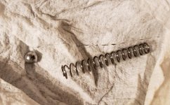
I removed the hose and it spit out some hydraulic fluid, a spring, a steel ball (and who knows what else? I did not find anything but I wasn't ready to catch anything, I didn't think it would be under some residual pressure)

See pictures below. I searched long on the Internet but the diagrams I've found do not show any spring like this. How do I put it together correctly? I am not in the mood to take chances as I plan to put thousands of PSI into this...

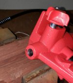
This is the portapower output, where I removed the 1/4" NTP hose
pump04.jpg

A better view of inside:
pump05.jpg

This is what came out (I hope I didn't miss anything, I wasn't exactly in the cleanest spot when I did this):
pump06.jpg

Detail of the hose fitting for reference:
pump07.jpg
 

Attachments

  • pump04.jpg
    pump04.jpg
    87.7 KB · Views: 29
  • pump05.jpg
    pump05.jpg
    106 KB · Views: 38
  • pump06.jpg
    pump06.jpg
    95.4 KB · Views: 36
  • pump07.jpg
    pump07.jpg
    83.9 KB · Views: 34
Last edited:
To avoid these ads, REGISTER NOW!

sick467

Well-known member
Joined
Jul 11, 2012
Messages
269
Location
Hughesville, Mo
Don't count me as an expert on this, but this is what I would do....I don't think you are missing anything. The ball goes into the pump first, then the spring. It acts as a check valve. The twist handle on the pump opens a port that will bypass the ball when you want to relieve the pressure that you have built up and the fluid bleeds back into pump housing.

The only thing I cannot determine is if the spring has a taper and would have to go into the pump a particular direction. The spring needs to touch and push up against the ball when the ball is touching its seat inside the pump. The pumped fluid will push past the ball (overcoming the spring pressure) building backpressure in the tool and line. This back pressure pushes back on the ball, pushing the ball up against its seat not allowing the fluid to flow backwards. The twist handle allows the fluid to flow back when your done. You can see how putting the ball and spring in the opposite way would defeat the purpose.
 
To avoid these ads, REGISTER NOW!
OP
M

manoweb

Well-known member
Joined
Oct 9, 2013
Messages
97
Location
California
The ball goes into the pump first, then the spring. It acts as a check valve. The twist handle on the pump opens a port that will bypass the ball when you want to relieve the pressure that you have built up and the fluid bleeds back into pump housing.

Yeah it makes sense, I see the return port that is positioned "externally" to the place the ball would sit inside...

The only thing I cannot determine is if the spring has a taper and would have to go into the pump a particular direction. The spring needs to touch and push up against the ball when the ball is touching its seat inside the pump.

The spring is not 100% symmetrical but I do not really see a taper. I cannot imagine it should make a difference, now that I kind of understand the mechanism. I just have to check what the spring is pushing against to in order to act as a check valve now that I want to install a tee.
 
To avoid these ads, REGISTER NOW!
Top Bottom