To avoid these ads, REGISTER NOW!

Air Compressor & Magnetic Switch

WX4SNO

Active member
Joined
Sep 17, 2017
Messages
32
Location
Snowville, VA
Just installed my new Ingersoll Rand 60 gallon air compressor and wired up a Shihlin Magnetic Starter (P35T). I followed the directions for wiring with the help of this Youtube video:

My magnetic switch has a green ON and a red OFF button. I pressed the green ON button and the compressor started up (with the pressure switch in the on/auto position); after breaking-in for 30 minutes with no load, I then closed the valve and let it build up pressure. However, the motor did not kick off and the pressure-relief valve opened...I had to press the red OFF button to turn the unit off. I tried it again, after releasing some air, but this time with the pressure switch in the off position...and it did the same thing.

It seems like I have to manually press the magnetic switch ON and OFF buttons because the pressure switch is not working. Does anyone know what might be wrong?? I'm attaching some photos of the wiring setup. Obviously I can't use it like this. At first I thought it might be because I have the on/off buttons on the magnetic switch, but shouldn't the pressure switch be kicking this thing off when it reaches 135 psi?

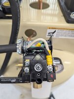
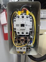
CURRENT WIRING (photos attached): The pressure switch L1 (black wire) is wired to the magnetic switch 1L1 and the pressure switch T1 (white) is running to A2 behind the 1L1 connection in the magnetic switch, per instructions. I have the motor wired to 2T1 and 6T3 via the bottom connections and the incoming power is going to 1L1 and 5L3.​
 

Attachments

  • PXL_20250703_173944077.MP.jpg
    PXL_20250703_173944077.MP.jpg
    105.1 KB · Views: 21
  • PXL_20250703_190052348.MP.jpg
    PXL_20250703_190052348.MP.jpg
    107.8 KB · Views: 22
  • PXL_20250703_190057538.MP.jpg
    PXL_20250703_190057538.MP.jpg
    125.1 KB · Views: 20
To avoid these ads, REGISTER NOW!

mm08822

Well-known member
Joined
Jan 13, 2012
Messages
5,895
Location
NJ
Sounds like you are wired for 3-wire control typical of start/stop momentary push-button.

Using a pressure switch typically requires 2-wire control scheme. Sometimes a maintained On/off selector switch is used in series with the pressure switch.

3-wire control means once the start pb is pressed, the contactor seals itself in to run using an auxiliary contact. The sealing contact holds the contactor in an energized state once you let up on the start pb.
The stop pb has to be pressed to break the sealing circuit.

Probably you ps isn't doing anything for control.

Need details around the start/stop pb wiring that you have.

Edit: unfixed the AI fix.
 
Last edited:
OP
W

WX4SNO

Active member
Joined
Sep 17, 2017
Messages
32
Location
Snowville, VA
So the magnetic switch ON button (black push-button on left side) is wired (via the yellow jumper) to 14 NO and this in turn has a yellow jumper running up to A2; and then I have the T1 from the ps connected to A2 as well.

The OFF button (right side) is wired via yellow jumper to 1L1. 1L1 also has two other wires connected: L1 from the ps and 1-leg of incoming power; the other leg of incoming power goes to 5L3 (nothing else connected here).

There is a neutral/middle yellow wire which jumps to 13 NO.

Maybe these pics will help a little better.
 

Attachments

  • PXL_20250703_222146716.MP.jpg
    PXL_20250703_222146716.MP.jpg
    127.6 KB · Views: 18
  • PXL_20250703_190108184.MP.jpg
    PXL_20250703_190108184.MP.jpg
    104.6 KB · Views: 19

TurnipTruck

Well-known member
Joined
Aug 28, 2005
Messages
1,557
Location
Southcentral Alaska
When troubleshooting electrical issues, the first step is drawing out an “as found” schematic to clarify each circuit.
I don’t see anything obvious wrong. Don’t assume something is good just because it’s new, either.
 

mm08822

Well-known member
Joined
Jan 13, 2012
Messages
5,895
Location
NJ
So the magnetic switch ON button (black push-button on left side) is wired (via the yellow jumper) to 14 NO and this in turn has a yellow jumper running up to A2; and then I have the T1 from the ps connected to A2 as well.

The OFF button (right side) is wired via yellow jumper to 1L1. 1L1 also has two other wires connected: L1 from the ps and 1-leg of incoming power; the other leg of incoming power goes to 5L3 (nothing else connected here).

There is a neutral/middle yellow wire which jumps to 13 NO.

Maybe these pics will help a little better.
You have 3wire control and 2wire control simultaneously connected.

Disconnect each of the 3 wires going to the switches.
 

wyliesdiesels

Well-known member
Joined
Aug 14, 2012
Messages
19,998
Location
Modesto, CA
The green and red buttons need to be disconnected

You should only have the pressure switch connected to one side of the coil and the overload relay to the other side

The off/auto switch can be wired in series between one of the above and one side of the coil.
 
Last edited:
To avoid these ads, REGISTER NOW!

BillK

Well-known member
Joined
Aug 24, 2006
Messages
9,320
Location
Beautiful Southern Maryland
Which model compressor do you have ? That would make it a lot easier to look at the wiring diagram. Actual diagrams are so much easier to follow compared to pictures when it comes to electrical troubleshooting.
 

mm08822

Well-known member
Joined
Jan 13, 2012
Messages
5,895
Location
NJ
Remove the wires in red. Your pressure switch should be connected across 1L1 and 14 or 1L1 and A2. A2 preferred over 14.
Does your PS have an on/off lever?
1751651666773.png
 

wyliesdiesels

Well-known member
Joined
Aug 14, 2012
Messages
19,998
Location
Modesto, CA
Which model compressor do you have? That would make it a lot easier to look at the wiring diagram. Actual diagrams are so much easier to follow compared to pictures when it comes to electrical troubleshooting.
i dont think the starter came with the compressor so that wont work
 
OP
W

WX4SNO

Active member
Joined
Sep 17, 2017
Messages
32
Location
Snowville, VA
No, the starter did not come with the compressor. After hearing all the fail rates of the pressure switches for these, I figured I'd buy a dedicated magnetic unit; my mistake was getting the one with the on/off push buttons rather than the P30T which is what is shown in the instruction video.

I was able to get it wired up by bypassing the push-buttons on the magnetic starter. It was trial-and-error on my part until about midnight Thursday (prior to most everyone's responses, but thank you nonetheless!) and I'll have to open it back up and respond with what I actually did. I've put the compressor through its break-in cycle and have already done some sand blasting with it...working good now!
 

aalleexx

Well-known member
Joined
Apr 22, 2008
Messages
136
Location
East Texas
No, the starter did not come with the compressor. After hearing all the fail rates of the pressure switches for these, I figured I'd buy a dedicated magnetic unit; my mistake was getting the one with the on/off push buttons rather than the P30T which is what is shown in the instruction video.

I was able to get it wired up by bypassing the push-buttons on the magnetic starter. It was trial-and-error on my part until about midnight Thursday (prior to most everyone's responses, but thank you nonetheless!) and I'll have to open it back up and respond with what I actually did. I've put the compressor through its break-in cycle and have already done some sand blasting with it...working good now!
I am in the same boat with the same mag starter looking to wire in a pressure switch for my second hand bought compressor from a disconnect. Would appreciate seeing how you ended up doing yours for guidance with mine.
 

nadogail

Well-known member
Joined
Jan 23, 2009
Messages
31,938
Location
Coronado, CA
When you try to build a control system with mismatched controls you probably should rethink your design.
 
To avoid these ads, REGISTER NOW!
Top Bottom