To avoid these ads, REGISTER NOW!

Air compressor - reed valve replacement

stickshift

Well-known member
Joined
Nov 16, 2011
Messages
1,215
Location
northeastern US
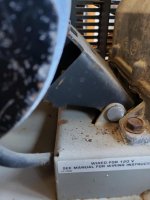
I picked up an old compressor for cheap. The air filter being used was some old dirty foam. I temporarily replaced this with some house air filter material (this was a mistake, as you will see). Compressor seemed to be running OK.

With the help of @Jswain and @The Cobbler in another thread (on drain valves) I determined that a reed valve is broken. By the time I had figured this out, an edge from the air filter material I used got sucked into one of the intake ports. I attempted to start the compressor while pulling on the filter material, figuring I could pull it out when the port pushed air out (as this particular port was doing, hence the conclusion that reed valve is bad). Within a second or so of starting, the compressor sounded wrong, so I shut it off, and the motor kind of whined and trailed off until it was quiet. Not sure if I FUBAR'ed the compressor. :dunno:

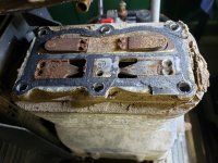
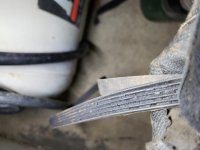
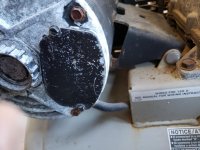
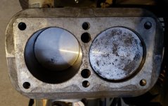
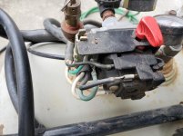
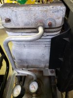
I've attached a few pics showing the intake ports, a closeup with the port with bad reed valve (you can see piece of broken off metal under the pick I'm holding) and the torn off bit of stuck filter material. Also a few pics of the pump.

At this point, I'll have to removed the pump's head(?) and get that filter material out as well as replace the reed valves and see what else is going on in there, before trying to restart the machine.

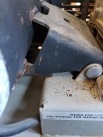
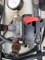
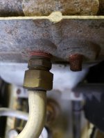
The metal hose that runs from pump to tank is secured to the fitting into the head via a nut (compression nut I guess?). This is shown in last pic. If I turn the smaller nut to loosen the fitting from the pump's head, the larger nut turns with it. Should I hold the larger (compression?) nut still while loosening the smaller nut?
 

Attachments

  • 2020-10-10 18.35.17.jpg
    2020-10-10 18.35.17.jpg
    149.2 KB · Views: 121
  • 2020-10-14 18.34.18.jpg
    2020-10-14 18.34.18.jpg
    151.1 KB · Views: 110
  • 2020-10-16 17.13.11.jpg
    2020-10-16 17.13.11.jpg
    72.2 KB · Views: 100
  • 2020-10-16 17.16.32.jpg
    2020-10-16 17.16.32.jpg
    106.4 KB · Views: 103
  • 2020-10-16 17.16.42.jpg
    2020-10-16 17.16.42.jpg
    108.7 KB · Views: 92
  • 2020-10-16 17.17.03.jpg
    2020-10-16 17.17.03.jpg
    93.2 KB · Views: 94
  • 2020-10-16 17.28.04.jpg
    2020-10-16 17.28.04.jpg
    73.1 KB · Views: 91
To avoid these ads, REGISTER NOW!
OP
S

stickshift

Well-known member
Joined
Nov 16, 2011
Messages
1,215
Location
northeastern US
No identifying marks on the pump (unless there's one on the side facing the belt) other than this.
 

Attachments

  • 2020-10-16 17.47.04.jpg
    2020-10-16 17.47.04.jpg
    151.8 KB · Views: 64

Jswain

Well-known member
Joined
Apr 26, 2013
Messages
2,457
Location
Calgary, AB
Definitely hold the bushing going into the head with another wrench as if they both spin you will twist and ruin the metal pipe(ask me how I know)

It is a pretty simple and straight forward repair if you can find the parts. Either buy the gaskets or make them out of some Garlock 3000 1/16 thick most likely.

Should be able to search by the tag on the tank to find parts if there is a model or even a make and then Google image search to find the same unit
 
OP
S

stickshift

Well-known member
Joined
Nov 16, 2011
Messages
1,215
Location
northeastern US
(ask me how I know)
Yeah, I know them feels! Have learned many lessons wrenching firsthand that I wish I could have learned secondhand.

Got the head off. Can clearly see the broken intake valve (where the little bit of filter material is snagged), so that explains why the intake was blowing out with each piston cycle.

And there's the valve plate. This is stuck onto the gasket which is stuck onto the crankcase. I tried to gently persuade the plate off using a punch and a mallet against side of plate. Didn't budge. Then tried wedging a cheap drywall knife under the gasket and tapping with hammer but nothing doing. Before I pound that plate off and possibly screw the pooch, I figured I'd check here to see if there's a better way to separate this plate from the crankcase.

Link to diagram of pump.
 

Attachments

  • 2020-10-16 21.08.51.jpg
    2020-10-16 21.08.51.jpg
    154.3 KB · Views: 125
  • 2020-10-16 21.09.10.jpg
    2020-10-16 21.09.10.jpg
    155.7 KB · Views: 131
Last edited:

1931S/X

Well-known member
Joined
Sep 16, 2007
Messages
143
That looks very similar to a compressor i have. There should be a sticker on the tank from the actual manufacturer. If it's the same they were rebadged for all kinds of companies.my dad bought mine from IR in the early 90s. I finally had to replace the reeds like 2 years ago. it seemed like that stuff is getting hard to find like they weren't supposed to last this long. I got them on ebay.
 

The Cobbler

Super Moderator
Staff member
Joined
Oct 24, 2013
Messages
25,836
Location
Niagara Region, Ontario, Canada
I think they were devilbiss pumps. and I've heard of guys making new reed valves with feeler gauges .
you have the head off,
you may need more force on that plate but you don't need to remove that to replace the reeds
yes, use 2 wrenches on the nut & fitting.
 
Last edited:
OP
S

stickshift

Well-known member
Joined
Nov 16, 2011
Messages
1,215
Location
northeastern US
You might try dropping some rope down through the valve port and try to gently tap the plate off with one of the pistons by hand.
Parts available here, but.....there are several pumps which look like your but with different part numbers. It might take some digging.

https://mastertoolrepair.com/devilb...243_90.html?osCsid=8tp28dnfvpjcf4bbffai67jua8
I figured out what I was doing wrong - there's a molding that's part of the crankcase that I assumed was the gasket - that's what I was trying to wedge the drywall knife under, unsuccessfully of course. The actual gasket is curved like the valve plate and sits between that crankcase molding and the valve plate. But, since I've got access to all the reed valves, doesn't seem like I need to remove the valve plate. That would be just another just another two surfaces to scrape clean (underside of valve plate and top of crankcase) and another gasket to buy.
 
Last edited:
OP
S

stickshift

Well-known member
Joined
Nov 16, 2011
Messages
1,215
Location
northeastern US
I think they were devilbiss pumps. and I've heard of guys making new reed valves with feeler gauges .
you have the head off,
not sure if there's another plate or not. you may need more force
yes, use 2 wrenches on the nut & fitting.
No, I just wasn't seeing it correctly - see my prior post. I can see the gasket now. But since I have access to the reed valves, maybe not much point in removing the valve plate - just another two surfaces to scrape clean (underside of valve plate and top of crankcase) and another gasket to buy. I just want to get this running close to spec; not trying to rebuild an old compressor that can be bought all day long for relatively cheap.

I'm thinking all the crud that falls into the cylinder while I'm scraping the top of the valve plate clean can be vacuumed out?

Pic of top of valve plate with reed valves removed.

Yeah, I saw a video where a guy used feelers. I have a set of feeler gauges, but they're a fair bit narrower than the reeds. So if I use these, they won't fully block the ports. Don't think I have any other super thin spring steel laying around. So instead of messing around with a DIY solution that is unlikely to work, I'll just buy the correct reed valves.

These plate restrictors sit on top of the exhaust (pressurized air) reed valves - I guess they function to prevent the reed valves from getting all bent out of shape from the pressurized air.
https://www.ereplacementparts.com/plate-restrictor-p-63245.html

Anyway these are quite a bit thicker than the reed valves. Seem in good shape apart from rust, so maybe I can just sand the rust off and apply a little silicone lube and reuse?

Pic of plate restrictor mounted over exhaust port reed valve.
 

Attachments

  • 2020-10-16 23.21.07.jpg
    2020-10-16 23.21.07.jpg
    150.2 KB · Views: 70
  • 2020-10-16 23.23.59.jpg
    2020-10-16 23.23.59.jpg
    152.4 KB · Views: 66
OP
S

stickshift

Well-known member
Joined
Nov 16, 2011
Messages
1,215
Location
northeastern US

Jswain

Well-known member
Joined
Apr 26, 2013
Messages
2,457
Location
Calgary, AB
These plate restrictors sit on top of the exhaust (pressurized air) reed valves - I guess they function to prevent the reed valves from getting all bent out of shape from the pressurized air.
https://www.ereplacementparts.com/plate-restrictor-p-63245.html

Anyway these are quite a bit thicker than the reed valves. Seem in good shape apart from rust, so maybe I can just sand the rust off and apply a little silicone lube and reuse?

Pic of plate restrictor mounted over exhaust port reed valve.

Should be pretty safe to reuse. No shame in doing a minimal repair. Clean everything up real well & reassemble with new gaskets/Reed valves. Torque up the head & change the oil. Retorque head bolts after a few cycles when it's cooled back down
 
OP
S

stickshift

Well-known member
Joined
Nov 16, 2011
Messages
1,215
Location
northeastern US
Actually, I think I'll go ahead and remove the valve plate. The place I'm getting the parts from - the only place I found selling the reed valves for a reasonable price AND has them in stock - has both gaskets for $4 apiece.

Any other wear and tear parts I should check or change while I've got the head off? Anything I should lube?

Belt looks OK, a little worn, but not fraying. Since that's a pretty easy replacement and doesn't require tearing down anything or redoing gaskets, I'll hold off on this for now. The reason the compressor stopped working as described in the OP is that the belt fell off, so the motor was free spinning. Flywheel seems reasonably easy to turn by hand and pistons seem to be moving OK. Not sure why belt came off, but I don't think I FUBAR'ed anything.
 

Attachments

  • 2020-10-17 01.21.06.jpg
    2020-10-17 01.21.06.jpg
    154.7 KB · Views: 44
  • 2020-10-17 01.21.36.jpg
    2020-10-17 01.21.36.jpg
    93.7 KB · Views: 37
  • 2020-10-17 01.23.59-1.jpg
    2020-10-17 01.23.59-1.jpg
    97 KB · Views: 40

MacMcMacmac

Well-known member
Joined
Oct 21, 2014
Messages
1,583
Location
canada
i'd be happy to trade off the extra work it took to clean the gasket surfaces against knowing there wasn't any debris left in the cylinders. That air filter had to be at the top of its game to keep all the **** out, according to the look of the outside of the pump. It would be nice to see if there was any scoring or oil carryover too.

Looks like the belt came off because the grooves are full of debris. At that point it's a flat belt running on a flywheel with no crown.
 
OP
S

stickshift

Well-known member
Joined
Nov 16, 2011
Messages
1,215
Location
northeastern US
i'd be happy to trade off the extra work it took to clean the gasket surfaces against knowing there wasn't any debris left in the cylinders. That air filter had to be at the top of its game to keep all the **** out, according to the look of the outside of the pump. It would be nice to see if there was any scoring or oil carryover too.

Looks like the belt came off because the grooves are full of debris. At that point it's a flat belt running on a flywheel with no crown.
Yeah, I agree on removing valve plate and making sure cylinders are free of debris.

I temporarily put the head back just to make sure the motor and pump will operate. It runs fine. Not sure why belt came off before as described in OP. I did use a different power source that time - previously I was using a 20A circuit that had nothing else on it. The time the belt came off was the one time I used a 15A circuit that has a number of other loads on it. Breaker wasn't tripped.

Anyway, before running it this morning, I put the belt back on, perfectly seated in grooves on both flywheel and motor pulley. As soon as it started spinning, the belt moved outward a little on the flywheel, but after that initial move, it stayed in its new location. So it's probably not a fatal issue, but it would explain why the belt looks the way it does, and probably means much shorter belt life.

Looks like the flywheel and motor pulley are in slightly different planes. Not sure how apparent it is in these pics, but the part of the flywheel that is farther away from the motor is further away from the compressor body than the nearer part of flywheel. I'll have to see what the manuals of similar compressors say about adjusting alignment (can't find manual for this particular compressor), but if anyone has experience with this, please let me know.
 

Attachments

  • 2020-10-17 10.53.35.jpg
    2020-10-17 10.53.35.jpg
    152.9 KB · Views: 35
  • 2020-10-17 10.51.31.jpg
    2020-10-17 10.51.31.jpg
    135.5 KB · Views: 35
Last edited:

Jswain

Well-known member
Joined
Apr 26, 2013
Messages
2,457
Location
Calgary, AB
Don't forget a new air filter!! Lol. Yes definitely make sure you leave the pistons & cylinders nice and clean. Inspect the walls of the cylinders. Inspect the oil level in the pump if it's down low and you find some oil on top of the pistons it might be time for a ring job but chances are you will be ok.

Check all surfaces with a straight edge before reassembly

For the pulleys clamp a straight edge to the outside flats of the large pulley and then adjust the motor by loosening the mounting bolts and pulling/pushing it back straight so that both pulley & the belt both run parallel with the straight edge.

It's sometimes easier to pull it back with the belt snug, tighten up one bolt on the opposite side of the belt, then pull back and tighten up the belt side, or you can use a block of wood cut in between the two pullies, or I sometimes use bar clamps reversed to push. If you need to go left or right you may have to adjust the pulley on the motor in or out on the shaft
 
Last edited:
OP
S

stickshift

Well-known member
Joined
Nov 16, 2011
Messages
1,215
Location
northeastern US
For the pulleys clamp a straight edge to the outside flats of the large pulley and then adjust the motor by loosening the mounting bolts and pulling/pushing it back straight so that both pulley & the belt both run parallel with the straight edge.
There are no motor mounting bolts. There is a bracket that is welded to the motor and the bracket is on a hinge attached to the welded platform that the pump is secured to.

With belt removed, the bracket rests on the platform (and the motor body is just a fraction of an inch above the tank). With belt on, the belt suspends the motor such that bracket is no longer touching the platform. This means the weight of the motor is held up by the belt. That seems odd. There is a hole in the bracket - perhaps there is meant to be a bolt or threaded rod here with a nut underneath the bracket that is used to support the weight of the motor when the belt is on?

Pics below. The pic with the bracket lifted off the platform is where I'm holding the motor up - which the belt does when it is installed. That can't be right because then the belt is not only transferring the torque of the pulley to the flywheel, but also holding the motor up - that would be a very strange design. :dunno:

With the way the motor is mounted, there doesn't seem to be a way to make side-to-side rotational adjustments of the motor pulley relative to the flywheel since the only attachment point of the motor to the compressor is the hinge pin that runs through motor bracket. I'll see if sliding the motor pulley outward a touch allows the belt to stay in the grooves.

Ah, there are missing parts. Looking back at the parts diagram, there is supposed to be a screw hold down (looks like a "L" shaped threaded rod (kind of like a car battery hold down bolt), spring elastomer, washer, lockwasher, and wingnut. Looks like all those parts except for "screw hold down" sit above bracket, so I'm not sure how they support the weight of the motor. But I can see how they would apply tension to the belt, by pushing the motor away from the flywheel as you tighten the wingnut.
 

Attachments

  • 2020-10-17 12.07.48.jpg
    2020-10-17 12.07.48.jpg
    98.5 KB · Views: 42
  • 2020-10-17 12.08.10.jpg
    2020-10-17 12.08.10.jpg
    147.7 KB · Views: 46
  • 2020-10-17 12.09.21.jpg
    2020-10-17 12.09.21.jpg
    81.1 KB · Views: 42
  • 2020-10-17 12.11.31.jpg
    2020-10-17 12.11.31.jpg
    65.7 KB · Views: 43
Last edited:

Jswain

Well-known member
Joined
Apr 26, 2013
Messages
2,457
Location
Calgary, AB
Ahh gotcha, older craftsman tablesaws are setup similiar with the belt holding the weight of the motor up on a pivot and it works fine. See if you can get a little wiggle out of the pump then with its mounting bolts to get it parallel and then adjust the pulley on the shaft for left to right
 
OP
S

stickshift

Well-known member
Joined
Nov 16, 2011
Messages
1,215
Location
northeastern US
Ahh gotcha, older craftsman tablesaws are setup similiar with the belt holding the weight of the motor up on a pivot and it works fine. See if you can get a little wiggle out of the pump then with its mounting bolts to get it parallel and then adjust the pulley on the shaft for left to right
Good call. There was a tiny bit of play on the pump once I loosened the pump mounting bolts. Still out of alignment, but a little better.

And a lot better in terms of the belt behavior. Before this, as soon as the motor started, the belt partially jumped out of the grooves and then stabilized. Video from before adjustment.


After the slight tweak, the belt runs in the grooves. Video of this. When I turned it on, I had my knee on the motor to put some tension on the belt. ~30 seconds in, I took my knee off the motor and the belt still stays in place, though the motor bounces a little bit more, so I'll need to track down a screw hold down so I can maintain proper tension on the belt.


As you can see, alignment is still a little off. Might make it a little better if I could slide the motor pulley out a touch, but it's seized up pretty good on the spindle unless there's something holding it in besides the set screw which I backed off a few turns. Tried pulling on the pulley while tapping the end of the spindle with a hammer, but pulley didn't budge. I just put a little Liquid Wrench on either side of the pulley where it contacts spindle, so I'll try same method later after giving this a chance to soak in, unless someone has a better suggestion.

Not worth going nuts over, or risking making things worse, since at least now the belt stays in the grooves, so I'm sure belt life will be greatly improved. The marginal improvement I might get with the pulley slid out a touch would be nice (further improve belt life) but only if not much hassle involved.
 
To avoid these ads, REGISTER NOW!

Jswain

Well-known member
Joined
Apr 26, 2013
Messages
2,457
Location
Calgary, AB
You could try tapping it in slightly using a socket just larger than the od of the shaft. Then if any of the shaft is exposed clean it with some sandpaper or a scotch bright pad then lube and go back to tapping on the end of the shaft while pulling out. This should break the corrosion and get it moving just avoid tapping/prying etc on the OD of the pulley or it will mangle quick.
If you have a 2 or 3 jaw pulled it could be used as well but can still damage the pulley, but I would still try to drive it in a bit first, clean the shaft then pull it out.
 

The Cobbler

Super Moderator
Staff member
Joined
Oct 24, 2013
Messages
25,836
Location
Niagara Region, Ontario, Canada
sounds like you're on the right track for sure . the belt alignment on those multi ribbed belts is more critical than a v belt. . on mine I ended up swapping the belt end for end and it stayed on just fine for several months , then it was toast & i replaced it .
 
OP
S

stickshift

Well-known member
Joined
Nov 16, 2011
Messages
1,215
Location
northeastern US
You could try tapping it in slightly using a socket just larger than the od of the shaft. Then if any of the shaft is exposed clean it with some sandpaper or a scotch bright pad then lube and go back to tapping on the end of the shaft while pulling out. This should break the corrosion and get it moving just avoid tapping/prying etc on the OD of the pulley or it will mangle quick.
If you have a 2 or 3 jaw pulled it could be used as well but can still damage the pulley, but I would still try to drive it in a bit first, clean the shaft then pull it out.
It was worth a shot, but socket + tapping w/ hammer didn't budge the pulley. I suppose using a torch is another option to break it free, but since the belt now stays in the grooves, I'm gonna call it good enough and move on.

So the motor hold down parts (that hold the motor down and thereby tension the belt) aren't available at the parts website that has the reed valves in stock, so I'll just piece that together from hardware store. The "screw hold down" looks fairly similar to a J bolt, so this might work. Failing that, I can get a battery hold down bolt, cut it short and bend it. Washer, lockwasher and wingnut are self-explanatory. That leaves the "spring elastomer". Is this just a rubber washer? I guess this serves a slight dampening function to reduce vibration to the motor.
part_p_63225_3093491916.gif
 
OP
S

stickshift

Well-known member
Joined
Nov 16, 2011
Messages
1,215
Location
northeastern US
I've got all the mating surfaces cleaned up (head, both sides of valve plate, crankcase). Never prepared surfaces to contain high pressure air before, so I'm not sure when to stop; seems like I could keep going over these with a razor blade and remove tiny fragments of old gasket for hours. But I'm hoping that's unnecessary. What should I be aiming for - call it good when all surfaces are smooth to the touch?

There are some scratches from the razor blades, but I'm guessing once the gasket is compressed, those scratches will get filled in?

On a related note, I watched a video where someone uses a die grinder and a special gasket removing attachment. Holy moly, that was quick! After I get this compressor up and running, I'm getting a die grinder; I don't ever want to use razor blades to remove old gasket material again.
 

Attachments

  • 2020-10-21 18.21.16.jpg
    2020-10-21 18.21.16.jpg
    153.9 KB · Views: 33
  • 2020-10-21 18.20.56.jpg
    2020-10-21 18.20.56.jpg
    152.7 KB · Views: 35
  • 2020-10-21 18.20.29.jpg
    2020-10-21 18.20.29.jpg
    152.5 KB · Views: 34
  • 2020-10-21 18.19.51.jpg
    2020-10-21 18.19.51.jpg
    151 KB · Views: 37

Jswain

Well-known member
Joined
Apr 26, 2013
Messages
2,457
Location
Calgary, AB
Yes the 3m bristle discs are amazing on a die grinder at removing gasket material. Looks clean enough to me and yes those baked on gaskets can be a b*tch to remove with a razor blade lol
 
OP
S

stickshift

Well-known member
Joined
Nov 16, 2011
Messages
1,215
Location
northeastern US
Yes the 3m bristle discs are amazing on a die grinder at removing gasket material. Looks clean enough to me and yes those baked on gaskets can be a b*tch to remove with a razor blade lol
Yeah, that was miserable! I did a search about halfway through to see if there was a better way and that's when I discovered those die grinder discs. But the catch is you need a working air compressor! Seeing that made going back to the razor blade even worse. Never again!

Thanks for taking a look. Should receive the gaskets and other bits by the weekend, so I'll seal it up and hope for the best.
 

goodwrench

Well-known member
Joined
Oct 21, 2006
Messages
172
milwaukee has cordless die grinders that are great when your air compressor is broke���� and you need a die grinder to help fix it.
 
OP
S

stickshift

Well-known member
Joined
Nov 16, 2011
Messages
1,215
Location
northeastern US
the surfaces look good
you can also rub the flat surfaces on a flat surface using 400 paper to clean up any small stuff
Good call. Finest I had was 220 grit, so I added water to wetsand. That helped flatten out any scratches from using razor blades to scrape off the old gasket material.
 
OP
S

stickshift

Well-known member
Joined
Nov 16, 2011
Messages
1,215
Location
northeastern US
Trying to figure out what I should torque the pump head bolts to. Cannot find a manual for this model, but did find a manual for the identical Porter Cable C5510, but that doesn't provide torque specs.

Maybe 20ft-lbs?
 

redmondjp

Well-known member
Joined
Nov 25, 2014
Messages
2,318
Location
Redmond, WA
Trying to figure out what I should torque the pump head bolts to. Cannot find a manual for this model, but did find a manual for the identical Porter Cable C5510, but that doesn't provide torque specs.

Maybe 20ft-lbs?

For a 3HP Briggs & Stratton flathead engine that uses all aluminum parts and has 5/16" diameter bolts, the torque spec. is 15.5 lb-ft.

So I would say 16-18 lb-ft range.
 
OP
S

stickshift

Well-known member
Joined
Nov 16, 2011
Messages
1,215
Location
northeastern US
For a 3HP Briggs & Stratton flathead engine that uses all aluminum parts and has 5/16" diameter bolts, the torque spec. is 15.5 lb-ft.

So I would say 16-18 lb-ft range.
3/8" bolts and aluminum head and valve plate, so that range sounds reasonable, thanks.
 
OP
S

stickshift

Well-known member
Joined
Nov 16, 2011
Messages
1,215
Location
northeastern US
So I received the new reeds, gaskets and filters and got it all back together, and got a j-bolt and fasteners to get the belt tensioned. Running pretty good. Thanks for all the tips. :beer:

One thing I noticed is I don't hear the charging line pressure unloading after the compressor cuts out. There is an unloader line connecting the check valve to the pressure switch. What's a good way to test that the unloader is functioning, or diagnose where the issue might be?
 

The Cobbler

Super Moderator
Staff member
Joined
Oct 24, 2013
Messages
25,836
Location
Niagara Region, Ontario, Canada
the unloader is part of the pressure switch. when the switch opens(shuts off the motor) there's a tab that moves and presses on the unloader and releases the air . with the switch in the off or tank full position, the unloader line will not hold pressure if it's operating properly.
by chance when you were working around the unit you might have bent the tab or misaligned it . shoot some pics maybe
 

larry4406

Well-known member
Joined
Jan 27, 2006
Messages
19,075
Location
Northern Virginia
So I received the new reeds, gaskets and filters and got it all back together, and got a j-bolt and fasteners to get the belt tensioned. Running pretty good. Thanks for all the tips. :beer:

One thing I noticed is I don't hear the charging line pressure unloading after the compressor cuts out. There is an unloader line connecting the check valve to the pressure switch. What's a good way to test that the unloader is functioning, or diagnose where the issue might be?

On my compressor (Puma), there are two designs. One with unloader and one without. I am still waiting on parts for mine due to similar issue. The parts guy said either would fit but if the wrong reed valve set were installed, the unloader would not work. I use the "continuous run" feature when doing long blasting sessions.
 

Fialaja

Well-known member
Joined
Jan 4, 2018
Messages
732
Location
NJ
These older compressors can become quite the money pit. I rebuilt a trash pick compressor and between flex copper tube, fittings, paint, etc. well around 1- 2 hundred dollars....I had a reed valve that was cracked on mine.i wrapped it with HVAC duct tape. The silver foil type.
 
OP
S

stickshift

Well-known member
Joined
Nov 16, 2011
Messages
1,215
Location
northeastern US
the unloader is part of the pressure switch. when the switch opens(shuts off the motor) there's a tab that moves and presses on the unloader and releases the air . with the switch in the off or tank full position, the unloader line will not hold pressure if it's operating properly.
by chance when you were working around the unit you might have bent the tab or misaligned it . shoot some pics maybe
Yeah, I'm not hearing it releasing air. I took a few pics.

The unloader line connects to bottom of pressure switch. Where should it be releasing the air - inside the pressure switch enclosure?

Not sure how to remove the unloader to see if there's anything wrong with it. It's secured to underside of pressure switch enclosure by 2 torx screws. Would be very difficult to unscrew as is - just not enough clearance to work under there. Can I unscrew the four torx screws that go through the manifold portion of the pressure switch and into the enclosure for the electrical contacts, and separate the two halves of the pressure switch? Or is that a no-no b/c that would screw up the diaphragm?
 

Attachments

  • 2020-10-24 15.29.42.jpg
    2020-10-24 15.29.42.jpg
    153.4 KB · Views: 25
  • 2020-10-24 15.35.08.jpg
    2020-10-24 15.35.08.jpg
    106.1 KB · Views: 23
  • 2020-10-24 15.33.11.jpg
    2020-10-24 15.33.11.jpg
    84.2 KB · Views: 23
  • 2020-10-24 15.32.42.jpg
    2020-10-24 15.32.42.jpg
    92.6 KB · Views: 19
  • 2020-10-24 15.31.46.jpg
    2020-10-24 15.31.46.jpg
    96.6 KB · Views: 20
  • 2020-10-24 15.30.02.jpg
    2020-10-24 15.30.02.jpg
    147.3 KB · Views: 19
  • 2020-10-24 15.30.25.jpg
    2020-10-24 15.30.25.jpg
    148.7 KB · Views: 25

The Cobbler

Super Moderator
Staff member
Joined
Oct 24, 2013
Messages
25,836
Location
Niagara Region, Ontario, Canada
Try running the compressor, shut it off, crack a not on the unloader line & see if it has pressure in it.

look for a small tab on the other side of the unloader going into the switch & see if it moves when you turn the compressor on & off. the compressor can be unplugged for that test

As I'm typing, I'm wondering if a pc of that air filter got pushed into the unloader and is blocking it. pull the unloader line off the switch and see if air comes out when you turn on the compressor .

with the unloader line removed from the compressor , see if air will blow thru with the compressor in the off position.
 
To avoid these ads, REGISTER NOW!
Top Bottom