To avoid these ads, REGISTER NOW!

Air compressor remote switch

afazz

Well-known member
Joined
Nov 25, 2007
Messages
860
Location
Pittsburgh, PA
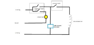
Basics: Air compressor in a closet under the stairs of a concrete two-story residential garage as illustrated below. 2017 NEC; 240v split phase residential power; copper THHN in EMT conduit.

I want to control the compressor with three way switches, one upstairs where I primarily work and one downstairs. I plan to achieve this by tapping into the pressure switch circuit, which controls the magnetic starter by switching one leg of the 240v circuit. I want to use pilot lighted switches so I can tell if the compressor is energized at a glance, whether I'm upstairs or downstairs. I also would like this all from the main compressor feed so I can throw the disconnect to shut down everything: compressor, pilot lights, and pressure switch. I'm sizing the feeders for a 7.5hp compressor, which I'm shopping for, but want to get operational with my current 2hp compressor.

Questions:
1) Is there a simpler way? I also have a magnetic starter and could potentially switch the coil voltage (which can be wired as 120v or 240v)
2) Neutral. I think I need a neutral for the pilot light switches, but would it have to be 6ga to match the power wires? Would I need a fuse somewhere to protect it, as it will not pass through the disconnect or magnetic starter?
3) Should I give up and throw a single pole switch on the mag starter coil and control it from upstairs only?


Compressor.jpeg
 
To avoid these ads, REGISTER NOW!

wyliesdiesels

Well-known member
Joined
Aug 14, 2012
Messages
20,025
Location
Modesto, CA
you would need to use a magnetic starter as you wont find 3-way switches that can handle the 2hp or 7.5HP motor load.

if you run the coil voltage at 240v you will need 277v rated (277v is what they come rated as) 3-way switches. not sure ive seen those in the stores

for the motor circuit wiring you will need 50a rated wire. since youre running EMT, #8 THWN is large enough.

as to the control wiring size, I would have to look it up as i dont know it off hand
 

larry4406

Well-known member
Joined
Jan 27, 2006
Messages
19,323
Location
Northern Virginia
I’ve been pondering similar as well.

Currently my head is gravitating towards the following 3-prong approach:

Part 1
Use normal 120V 3-way switches to control a switch plug and a status light you choose to indicate “On”.

Part 2
Use a RapidAir slow acting ball shutoff valve plugged into the switch plug and piped to the tank outlet. Compressor always has power and could run if there was somehow a demand but air is controlled on/off with a tight shutoff/isolation valve.

Part 3
Use a 120V contactor energized by the switch plug to make/break the pressure switch control wire.

With the above, when the switch plug is off - status light is off, shutoff valve is closed (tank pressure retained), and pressure switch wire is broken (unit can’t run). Air lines are free to leak down should there be bad joints.

When switch plug is hot - status light is on, isolation valve is open and airlines are charged, and pressure switch is enabled so unit can cycle as normal.

Only thing this doesn’t do is drop out the 120V switch plug circuit when the 240V compressor circuit breaker is killed that the OP wants. I’m sure the prior owner of my house would just use one of the hot legs and ground to create a 120V circuit off the 240V 😳.

Part 3 could also be modified to drop out the 240V feed to the unit vs just the pressure control wire.
 
Last edited:

exranger06

Well-known member
Joined
Aug 9, 2015
Messages
1,686
Location
CT
I've done something very similar to what you want to do, except I have just one switch. It switches the coil of the starter. The indicator light is on whenever the toggle switch is on. The indicator is light is 120V, so I ran a neutral wire to it. I attached a wiring diagram showing how it's hooked up. I ran #12 wire from the starter to the switch. The wire size depends on the size of the breaker feeding the compressor. #12 is good for up to a 60A breaker. #10 for up to a 90A breaker. Table 430.72(B), Column C. You don't need any additional fuses or breakers for the control wiring.
Anyway, assuming you can find some 3-way switches rated at 240/277V, it shouldn't be hard to wire it up.
EDIT: I just did a quick search, and apparently Leviton makes a bunch of 277V rated 3-way switches. In fact, most of the Decora style residential switches they sell at Home Depot are 277V rated! Who knew? They also have regular toggle switches: https://www.supplyhouse.com/Leviton...qMisYkbsIUE3XfOhBkE1zXpSzMsQiUmBoCQJgQAvD_BwE
 

Attachments

  • compressor wiring diagram.jpg
    compressor wiring diagram.jpg
    44.3 KB · Views: 38
  • compressor switch2.jpg
    compressor switch2.jpg
    107.7 KB · Views: 30
Last edited:
To avoid these ads, REGISTER NOW!
OP
A

afazz

Well-known member
Joined
Nov 25, 2007
Messages
860
Location
Pittsburgh, PA
Thank you all for the help! Table 430.72(B), Column C contains exactly the info I needed on the control wire size, I will just run 12awg hot/neutral/travelers to a three-way switch.

I am intentionally over-sizing from 8awg to 6awg because I have lots of 6awg leftover from a previous project.

The current 2hp compressor has a Dayton magnetic starter, which is connected to a pressure switch per the "Ext. 2 wire control" in the diagram shown under the cover of the magnetic starter.
MagStarter.jpg


Here is an image of the pressure switch itself. I will confirm with a meter whether this sees 240v or 120v, which will determine if I can use a Leviton 1203-PLC (which I have leftover from a previous project), 277v rated 1223-7PR if I can find 2 for a reasonable price, or the CS320-2W above with a separate 240v pilot light (https://www.mcmaster.com/2779K716/) as @exranger06 shows above.
pressureswitch.jpg
 

ycgoat

Well-known member
Joined
Mar 28, 2020
Messages
971
Location
S.E. Va
If you already have a magnetic starter that can use a 120v coil, add a 240v to 120v control transformer in the starter and break it through the 3 way switches. Idealy the starter will be a combination starter, meaning it is also a disconnect. I have gotten to the point that I do not run 1/2" conduit anymore to ensure I can always add and remove wires as needed.

Edit: That starter says to use the local start and stop buttons only, so the toggle switches would only be an enabling circuit. Also your pic shows it under some stairs, that is a big no no in the commercial world.
 

Citation

Well-known member
Joined
Jan 20, 2016
Messages
3,219
Location
Indy
I have an alternative to connecting the pressure switch to wiring in the wall. Put a relay in series with the pressure switch. You would need a relay that can switch 240V (based on what I'm seeing in your pictures).
Something like this might do
For safety this should be installed in a grounded or insulated box.

The input 12 V can come from something simple like a 12V wall transformer
https://www.amazon.com/dp/B01GD4ZQRS/?tag=atomicindus08-20

Now all you have to do is provide power to the 12V transformer. One way to do that to install a 3 way, 120V AC outlet near the compressor. You then switch power to the AC outlet. This is nice since you would then have an AC outlet near the compressor as well.

Alternatively, if you don't want to mess with the AC wiring, get a remote switched power strip or smart outlet etc.
https://www.amazon.com/dp/B01GD4ZQRS/?tag=atomicindus08-20

The remote power strip is nice since it would require no wiring in the walls. However, over time you have to mess with batteries in the remote etc.

Edit:I see you already have a magnetic starter
 
Last edited:
To avoid these ads, REGISTER NOW!
Top Bottom