GeorgiaHybrid
Well-known member
You can use a plumbing type torch, just make sure it is designed for use with MAPP gas and use that instead of a regular tank. If you have an oxy/fuel torch, it works a little quicker but costs just a TAD bit more...")


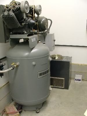


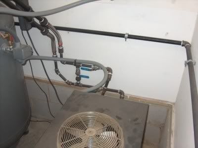
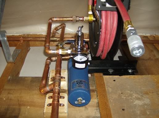
I did install a bypass with some SS ball valves in case I have issues with the dryer and need to remove it, I still will have air.
Air flow in piping is dependent upon the length of the pipe, the diameter, the number of bends, humidity, air temperature and the internal friction loss. Your 200 cfm pipe might do that in a 1 foot length. Make that pipe 200 feet long however with the typical turns that our home shops have and you might be lucky to get 50-75 cfm. Add in the restrictions on the couplers (they don't have a straight shot thru them), a rubber hose and restrictive inlets on the tools themselves and you can begin to understand why some of us plumb our systems the way we do.
I think you have just answered my question...folks use huge pipes because they don't know any better. Your post gives the best example, stating that "you may be lucky to get 50-75 cfm." I would be interested to know of anyone on GJ who has either a compressor that will put out that much air or a device that will use that much air. Your comment about the restrictive properties of the couplers, and tools themselves is the best indication that the oversized distribution system is a waste of money. Also the tool manufacturers are well aware of the inlet size and the air consumption rates of their products. If you have a tool with a 1/4 NPT inlet, connecting to a 4" line will not help you to realize any more performance from the tool. As I said earlier, look at the air passages of a HVLP gun than can flow around 12-15 CFM...do you see anything an inch in diameter there? A half inch? how about maybe .030". Don't waste your money doing things over the top, there are plenty of other details and features you can install in your garage to make it a fun functional, place.

I think you have just answered my question...folks use huge pipes because they don't know any better. Your post gives the best example, stating that "you may be lucky to get 50-75 cfm." I would be interested to know of anyone on GJ who has either a compressor that will put out that much air or a device that will use that much air. Your comment about the restrictive properties of the couplers, and tools themselves is the best indication that the oversized distribution system is a waste of money. Also the tool manufacturers are well aware of the inlet size and the air consumption rates of their products. If you have a tool with a 1/4 NPT inlet, connecting to a 4" line will not help you to realize any more performance from the tool. As I said earlier, look at the air passages of a HVLP gun than can flow around 12-15 CFM...do you see anything an inch in diameter there? A half inch? how about maybe .030". Don't waste your money doing things over the top, there are plenty of other details and features you can install in your garage to make it a fun functional, place.
My main intent was to get people to think... This whole site has a pervasive "bigger is better" attitude. That type of thinking flies in the face of what we are expected to do on so many different levels in our everyday lives. None of us would be to popular with our employers or our customers if we just threw the biggest most expensive equipment at every task that was assigned to us. When we are faced with making or designing something for the people that pay us, we need to be accurate, and have sound technical reasons for the solutions we implement. Not providing adequate reason, (other than the "because I can") for doing a task a certain way does not serve to help anyone who is truly interested in not only doing something for himself, but also to gain a working knowledge that can be applied to the next project. Do you run big air lines because they are warranted for your application or just because they need to be bigger than the other guys, or because you don't have a clue as to how to properly engineer your way out of a problem?I can certainly agree with that!This whole site has a pervasive "bigger is better" attitude.


And NO, PVC is not what anyone needs for airlines...

I put that in just for you!!!But PVC will work for airlines...
I put that in for Merk...."if 38DD are good then the 40EE are better"
OF COURSE THEY ARE!!! What the hell is wrong with you!!
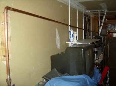
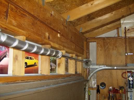
Can you explain these terms "free air" and "dead air space" in this context? ThanksAir lines are placed in free air at least 8" below the ceiling to keep them from being in a dead air space.

The lines in my shop have never been warm even after running the 9" Mud Hog until there wasn't enough air to keep it running, letting it rebuild pressure and run it down again.
I will say it again - I think many of you are not working from practical experience, or are running oiless compressors with way too small of a tank for the demands that you put onto your system.
I once worked in a body shop that had a monster of a compressor probably on the order of 20-30 HP, no dryer/chiller and just a maze of 3/4" black iron pipe, the paint shop drops were first off the compressor and air there wasn't warm. The discharge pipe from the compressor was but once through the tank it had cooled to ambient. This compressor could come up to pressure if a hose popped the end off and was whipping around.
Heresay and opinions are nice, -but... I am talking about accepted professional design standards in use in hundreds of thousands of installations for many years. If that is not enough practical experience I don't know what would be. Certainly it is better than anecdotal evidence from a handful of systems or less. The heat that is dissipated may only be the result of cooling a few degrees but it makes a difference in the dew point and hence moisture condensation, -simple physics. Air or gasses always cool when they expand, -again simple physics. The reservoir is the main cooling element in the system with its large surface area. The distribution lines are secondary but they are an important part and must be installed properly for optimum performance, moisture separation, and removal. Large industrial systems are designed by fluid power engineering professionals. They use many of the same principals as the home/small shop uses when they design those systems. Since a home/small shop does not usually have an engineer to design the system a "cut and paste", or "cookie cutter" method is used to provide a standard design for those systems. The standardized designs for home/small shops have been refined over the course of many years. Do not dismiss that experience out of hand because you do not understand the reasons for parts of it.
As to oversizing and the Bigger is Better theory I always thought that it was cheaper and stronger to go to the next size higher than to pay an engineering fee. -Ed
Take care Ed, the bigger the size the lower the pressure rating all else remaining the same. (as can be seen in the engineering data tables of Copper.org given above) Checking with an engineer can be a GOOD thing at times.
Thanks! Makes sense for water but does that apply to air as well?
Those are properties for the copper tube (material properties) makes no difference how the pressure is applied, be it by air or water. Pounds per square inch (psi.)
Well, the only two things that are different in whether it is for water or air is the amount of stored energy and temp changes due to compression/expansion. Yes both can have the same pressure, the difference is how they blow something apart. In the pipeline industry we're concerned about toughness of pipe, which plays into the equation when you think of what will happen when a pipe does have a flaw in it. A pipe with low toughess will exhibit brittle fracture (as what happens when PVC fails, it explodes), meaning it will completely fail and the crack tip will continue to propogate. With tougher (more maleable, in this discussion an example would be copper)pipe, the crack will not propogate as easily, and the pipe will end up with a split in it but will have a better chance of not blowing apart. Back to the water/air question, the difference is when you have pressure from water on a pipe and create a hole in it, you will get out a relatively small amount of water in a short amount of time because water is incompressible. Whereas with air, you will get a higher volume of air to come out for a longer period of time. Sooo when a rupture does happen, ruptures from air are much more catastrophic than from liquid. The other differince I can think of is the concept of compression and expansion from a heat perspective. As others have pointed out, air will heat under compression, and cool under expansion, so these temps need to be in consideration when figuring materials.
Also is there any negative effects to using galvanized pipe? Know it is a no-no for natural gas but would it help to keep rust and debris to a min?
... Also is there any negative effects to using galvanized pipe? Know it is a no-no for natural gas but would it help to keep rust and debris to a min?