

You are using an out of date browser. It may not display this or other websites correctly.
You should upgrade or use an alternative browser.
You should upgrade or use an alternative browser.
Air outlets
- Thread starter DRJZ1974
- Start date
porschedude996TT
Well-known member
Unless we're talking Schedule 40 PVC ;~)
................and the circle is now complete....................
Have a Blessed Christmas everyone!
Please explain, I believe that PSI is PSI whether it be water, air, or Hersey chocolate Syrup.
Torque1st
MEMBER EMERITUS
Pressure is the same but the media and the container are not the same.Please explain, I believe that PSI is PSI whether it be water, air, or Hersey chocolate Syrup.
Water or Hershey syrup is nearly incompressible so if a pipe or vessel containing it breaks all you get is a trickle, very little energy release.
Air is compressible so when a vessel containing it breaks you get a huge rush of material, a large energy release.
If you want to experiment (not recommended), punch a hole in a can of green beans. Then punch a hole in a spray can. -Get the picture?
Metal is ductile so when a metal pipe breaks all you get is a hole or a split. It bends when deformed by external stress. (Drop that can of beans...)
PVC is brittle so when it breaks it shatters like glass. It shatters when it is deformed by external stress which can come from unplugging an air line, thermal changes, or impacts from tools or other items. Drop or hit a glass jar full of Mayo...
When PVC contains air under pressure it explodes sending sharp fragments at high velocity just like a fragmentation grenade. It has been known to explode spontaneously.
As for an experiment with pressurized brittle containers... I don't know of anything around the house in glass that is under air/gas pressure. It isn't safe... The closest I can come is a TV picture tube which is under high vacuum (basically ~15PSI external pressure) and implodes when broken. The fragments can be thrown a long distance when they bounce off each other. Light bulbs would be another example of an imploding object. Detonating a firecracker inside a glass Christmas ornament would be an example of a brittle object failing from internal pressure.
I DO NOT recommend performing these experiments. They are offered as examples only.
Last edited:
Torque1st
MEMBER EMERITUS
Vinko
Well-known member
. Check the websites that have air-line diagrams for more airline layout information. I think one is TP Tools and Oldsmobility. The links have been posted literally hundreds of times here and at other sites.
These terms are also listed in online dictionaries.
Yeah, I've seen them same posted here many, if not a hundred times.
Here's another one, just for the heck of it
")
http://www.mcmaster.com/#air-compressor-aftercoolers/=53y7qt
Free air is air that moves. Convection currents are needed to carry off the heat from the lines. Dead air spaces are areas where there is little or no air movement.
Speaking of free air, and not necessarily asking of you, but of anyone with insight or willingness to answer: I don't see the use a drip leg, be they 6" or 12", in effectively "separating" condensed water from the rest of the compressed air in an airline system. Here's a typical drop in my system. I have a "T" which is capped off.I suppose I could switch out the capped T for the drop itself, and replace where I currently have the drop with a drip leg. But what good would it do. The water vapor is going to go right out the drop. It's not like it prefers a drip leg

A close up:

A line of drops:

Last edited:
Torque1st
MEMBER EMERITUS
Here's another one, just for the heck of it
http://www.mcmaster.com/#air-compressor-aftercoolers/=53y7qt
That is not a very good diagram except for the position of devices, not the connections between them.
This is one of the best:
http://www.tptools.com/StaticText/airline-piping-diagram.pdf
It was "appropriated" and used at the oldsmobility site:
http://www.oldsmobility.com/air-compressor-piping.htm
Speaking of free air, and not necessarily asking of you, but of anyone with insight or willingness to answer: I don't see the use a drip leg, be they 6" or 12", in effectively "separating" condensed water from the rest of the compressed air in an airline system. Here's a typical drop in my system. I have a "T" which is capped off.I suppose I could switch out the capped T for the drop itself, and replace where I currently have the drop with a drip leg. But what good would it do. The water vapor is going to go right out the drop. It's not like it prefers a drip leg
Water in vapor form is carried by the air stream. Water in liquid form is conducted to reservoirs for draining.
The drip leg acts as a reservoir to collect the moisture that condenses on the pipe walls and runs down the downleg.
A drop should come off the TOP of the distribution line to avoid carrying the liquid water running along the bottom of the distribution line with the air.
Last edited:
krooser
Well-known member
Quote from Toprque 1st...
"If you want to experiment (not recommended), punch a hole in a can of green beans. Then punch a hole in a spray can. -Get the picture?"
Would it be OK to puch a hole in a can of corn?... it's nearly lunch time.
"If you want to experiment (not recommended), punch a hole in a can of green beans. Then punch a hole in a spray can. -Get the picture?"
Would it be OK to puch a hole in a can of corn?... it's nearly lunch time.
Torque1st
MEMBER EMERITUS
Yep!!!!Would it be OK to punch a hole in a can of corn?... it's nearly lunch time.

No Cents
New member
Pressure is the same but the media and the container are not the same.
Water or Hershey syrup is nearly incompressible so if a pipe or vessel containing it breaks all you get is a trickle, very little energy release.
Air is compressible so when a vessel containing it breaks you get a huge rush of material, a large energy release.
If you want to experiment (not recommended), punch a hole in a can of green beans. Then punch a hole in a spray can. -Get the picture?
I DO NOT recommend performing these experiments. They are offered as examples only.
Pressure is pressure. Your green beans were NOT under pressure, the spray can was. If the green beans were under the SAME pressure as the spray can the results would be very similar. The material, water, air, syrup, green beans doesn't really matter. The material doesn't have to be compressible to be under pressure. Obviously you have never worked on any hydraulic systems. I would NOT use PVC. Black Iron pipe is cheap and easy to work with.
Last edited:
Pressure is pressure. I would NOT use PVC. Black Iron pipe is cheap and easy to work with.
I wouldn't either.. PVC that is...
and DO NOT use threadless adaptors or connectors for pressure systems......
Shadowdog500
Well-known member
... If the green beans were under the SAME pressure as the spray can the results would be very similar. ...
I think Torque is talking about the fact that air can be compressed and water can not. When an air line ruptures, the air in all of the lines and tank will expand dramatically like an explosion. Water is not compressable, so when a line rupture occurs the pressure will drop almost immediately and not much water will come out.
Here is an experiment:
Pressurize the water system in your house and shut off the water pump. Open a faucet with a big bucket under it, and you should get a few gallons of water. Now close the faucet and plug in the water pump back in to pressurize your water system. Now shut off the water pump, and close the valve on your expansion tank. Open a faucet again with a glass under it, you will only get a few ounces of water this time. The water is under the same pressure both times but it does not expand like the air in the expansion tank does.
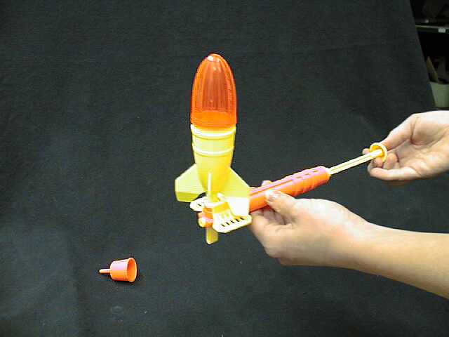
Here is another experiment that will simulate a rupture:
Take one of these rockets from when I was a kid (see photo) and pump it up with air until you cant pump anymore and pull the trigger. The rocket should fly up into the air because of the expanding air. Now put the rocket and pump under water, and fill the rocket completely with water and purge all of the air out of the pump and pump it up as much as you can. Now take it out of the water and pull the trigger. The rocket will probably go up about 1/4" before falling to the ground. Even though they were at roughly the same pressure the results will be dramatically different because one in highly compressed and the other is not.
Chris
Last edited:
e-tek
Well-known member
You guys have too much time on your hands....
Torque1st
MEMBER EMERITUS
Pressure is pressure. Your green beans were NOT under pressure, the spray can was. If the green beans were under the SAME pressure as the spray can the results would be very similar. The material, water, air, syrup, green beans doesn't really matter. The material doesn't have to be compressible to be under pressure. Obviously you have never worked on any hydraulic systems. I would NOT use PVC. Black Iron pipe is cheap and easy to work with.
Pressure IS pressure as far as force but the medium that is under pressure makes a HUGE difference in what happens when containment fails. Gasses under pressure are entirely different than liquids under pressure.
The green beans were not under pressure in the can. But whatever pressure there was, (probably vacuum) is released instantly. The spray can is under gas pressure which expands, keeping the contents under pressure until the pressure is equalized, or the can empties. Put the can of beans/corn in a vise if you want and squeeze it a little before you punch a hole in it. The filling is mostly liquid but it does have a small void.
Why do you think they test hydraulic components and pressure vessels with liquid under pressure rather than just filling them with compressed air? When a pressure vessel under test ruptures instead of exploding like a bomb it just goes "psst" and a small spray of liquid is released.
BTW, I have worked on and designed hundreds of hydraulic systems. 1/10HP to 4000HP. Mobile and industrial. I have also designed and worked on countless pneumatic machines and systems.
Last edited:
Torque1st
MEMBER EMERITUS
Probably not, these topics have been discussed a hundred times here and at every workshop forum on the net. Every time someone posts anything about air lines or compressed air systems instead of using the search function the same thing happens. Some (expletive deleted) person always chimes in that using PVC for air systems is safe because the pipe says ***-PSI on the side and they have been using it for X years... -You know the rest.Wow, all this from my air outlet question. Tons of hits on my thread. Wonder if it will become a sticky!!! Hahahaha

People in general seem to think cheap and easy is best so they try it.
I have seen the results when they did and it was not pretty.I was kidding about the sticky, just was surprised how many views the topic got. I did do a search and found nothing in terms of picture request specific to air outlets that people used in their air system. Most of this thread now has nothing to do with air outlets. Unfortunately the next person who searches this same topic and pulls this thread up will get a handful of good pics of air outlets and mostly debate about pressure. If anyone wanted a lesson in different forms of pressure, this would be the thread to view!
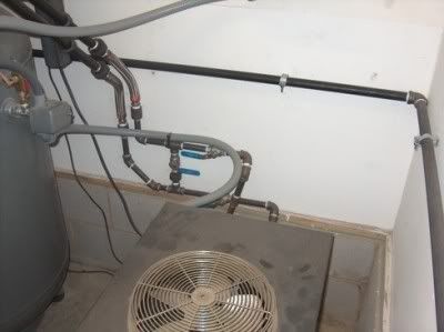
Starting at the air compressor, my system uses 3/4 black pipe around the perimeter of the shop, it slopes at 1" drop every 10' and has a timered drain at the end. All of the Outlets go up first, then out. This allows gravity to help in keeping water out of your tools (the outlets) and on the way to the end drain.
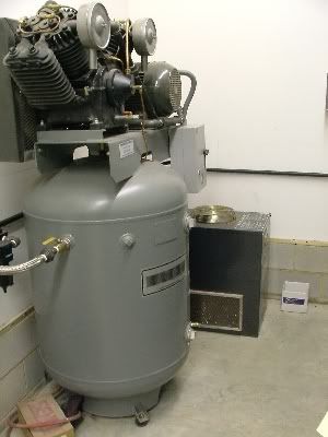


The pneumatech dryer is used inline with the pump in that the original plumbing from the compressor head to the tank was removed. It now is plumbed from the compressor head to the dryer, then back into the tank. I did install a bypass with some SS ball valves in case I have issues with the dryer and need to remove it, I still will have air. The starter switch on the compressor had an extra set of contacts, so the dryer was wired in there so it comes on every time the compressor does.
Hello, I've been following this post closely. I have an IR compressor with two 3hp/3 phase pumps/motors. A friend closed his businees and has given me the black pipe air lines from his shop. I'm not sure of the pipe size yet.
Is your Pneumatech unit a R12 system? When we're talking of sloping the air lines, does the line go up from the compressor? 930
Last edited:
MP&C
Well-known member
930, there are two lines of thought here, some who have an auto drain on the compressor only will tell you to slope the air lines uphill from that point, which would allow the water to drain back in the tank and use the same drain for ALL the water. Where my line if thinking is, why introduce any more water into the tank than you have to, less water causes less rust. I installed my air system before the dryer went in, so I did actually have water to deal with at one time. But the drain you see in my pictures is at the end of the run, mine slopes downhill from the point of the compressor. I would suggest not running the water back into the tank, why create more maintenance issues? Most people only have a petcock or ball valve under the compressor, so why not just add a ball valve at the end where it should be easier access, and you will have the length of the line to better condense out the moisture. And these next two items are cheap to install but give you so much better of an air system: Slope the water away to an automatic drain (or ball valve at the end), gravity helps to keep the water moving to the end and away from most of your outlets. Install all of your air outlets UP from the main line, and then you don't need a ball valve on each drop to drain out the water, there won't be any water in there. Again, gravity works in your favor to keep the water in the main line and flowing to the end drain. But this theory plays on two factors.
First, you must have enough of the (black steel) pipe run BEFORE the water traps to condense out the water so the trap can do it's job. Most mfr's recommend 25-50 feet minimum. If the heated air does not have enough chance to cool and condense, the water vapor will be carried right through your water trap until it does have a chance to cool. Finding water after your water trap would be a good indicator your "precooling" length of pipe is not long enough.
Second, Your pipe size must be of sufficient size that the air tool (device) is not drawing up the entirety of the supplied air, as in the case of too small an air pipe (downsizing outlets), as this will overcome the effect of gravity and draw up the water along with the air.
As far as the dryer, at the time of installation (which uses R22 BTW) I already had three water traps in my air system, one off the compressor (yes, I know it is too close) and two farther down the line at my paint booth outlet. Ever since the dryer has been installed (over 6 years ago), I have not had the first drop of water in any of the traps, or any come out while media blasting for hours on end. Well worth the expense. I found mine used online for a good price. When I installed it, I removed the copper feed tubing from the compressor head to the tank, and ran the compressor head directly to the dryer, with it's output going back into the compressor tank. If you're installing a system to dry your air, why not dry ALL of it before it gets in your tank?
While the dryer sure is nice to have, a well thought out air system will manage the water issues where the dryer is not such a neccessity.
Last edited:
DannyG
Active member
Cool info there Robert! I completely agree on sloping away from the tank, why not go with the flow and gravity and less in the tank, either way will work and some prefer to the tank.
Also have a simple and easy ball valve drain at the bottom. Made my own vibration isolators and anchored it into the floor. Now I have some ideas on what to do with that extra auto drain I have.

Also have a simple and easy ball valve drain at the bottom. Made my own vibration isolators and anchored it into the floor. Now I have some ideas on what to do with that extra auto drain I have.
red
Well-known member
Danny G, what did you use for vibration isolators? Did if make much of a difference? Thanks -Ed
DannyG
Active member
Hi Red! I don't feel the floor shaking as much than on wood, also less heat and vibration on the tank can only help. Like the longevity of the compressor as well. But I like to overdue things a bit. When I searched on prices of vibration isolators some can be expensive. So I found this left over carpet/rubber I used for amp racks and stereo systems from more than 10 years ago. I can't find it anymore, its just thin carpet of different colors now. The stuff was 1/8" thick and half of it was like rubber, I just improvised on a low budget. I'm sure theres much better ways. And at least its not eating into the concrete and can only help.
I'm using a loud single stage HF 15 amp thats on nearly the whole time with some tools. I tried hard looking for a single phase used 2 stage, but couldn't score one for the right price at the time. And sometimes you just need to get the job done with the funds you got. I found some more silly pics when making them. Maybe it will help you and others on better ways and ideas.


I'm using a loud single stage HF 15 amp thats on nearly the whole time with some tools. I tried hard looking for a single phase used 2 stage, but couldn't score one for the right price at the time. And sometimes you just need to get the job done with the funds you got. I found some more silly pics when making them. Maybe it will help you and others on better ways and ideas.
Vinko
Well-known member
Probably not, these topics have been discussed a hundred times here and at every workshop forum on the net. Every time someone posts anything about air lines or compressed air systems instead of using the search function the same thing happens.
While I appreciate your response to my questions in this thread
, and I don't want to sound ungrateful, I'm going to take issue with the whole Search Nazi mentality. If it's such a burden to see this reoccurring threads, why participate in them? Why not let the ignorant masses remain unenlightened? I'm willing to bet that even though, say, we've had countless threads on a particular general topic like "Snap On Tools" or "Plomb Tools" in the tool sub-section of this site, a new thread often generates those who have yet to participate, but might have something to contribute, an opportunity to do so. While often I'll research a question in the archives, often I'll resurrect a particular thread (adding to it) if I have a particular question in mind that I wasn't addressed or wasn't addressed fully.
I have a hard time comprehending this notion that the recurrence of topic or subject can provoke such a wearied view! Such exasperation! Such a beleaguered soul who must confront the same or similar topic at or near the top of a page of threads! Why not do away with message boards altogether!
engineer2
Well-known member
Just because you don't see moisture in your air lines or have dry drip legs doesn't mean there isn't any.
A couple of interesting articles:
http://www.plant-maintenance.com/articles/15_Rules_on_Condensation.shtml
Basics of Air dryers:
http://www.maintenanceworld.com/Articles/fpweb/dryingyour.html
Moisture in compressed air: (scroll down)
http://www.imionline.org/oldarticles2.html
A couple of interesting articles:
http://www.plant-maintenance.com/articles/15_Rules_on_Condensation.shtml
Basics of Air dryers:
http://www.maintenanceworld.com/Articles/fpweb/dryingyour.html
Moisture in compressed air: (scroll down)
http://www.imionline.org/oldarticles2.html
bohemianwelder
New member
Has anyone tried these kits from Eastwood?
http://www.eastwood.com/complete-garage-air-line-kit.html
http://www.eastwood.com/complete-garage-air-line-kit.html
RbrtAWhyt
Well-known member
Has anyone tried these kits from Eastwood?
http://www.eastwood.com/complete-garage-air-line-kit.html
HF has what appears to be the same kit for $99...
http://www.harborfreight.com/cpi/ctaf/displayitem.taf?Itemnumber=66747
Torque1st
MEMBER EMERITUS
Thanks for joining GJ. You can find many threads and a ton of information on those kits. Use the search function for "eastwood".
wineslob
Well-known member
Air flow in piping is dependent upon the length of the pipe, the diameter, the number of bends, humidity, air temperature and the internal friction loss. Your 200 cfm pipe might do that in a 1 foot length. Make that pipe 200 feet long however with the typical turns that our home shops have and you might be lucky to get 50-75 cfm. Add in the restrictions on the couplers (they don't have a straight shot thru them), a rubber hose and restrictive inlets on the tools themselves and you can begin to understand why some of us plumb our systems the way we do.
That is the exact reason for the diameter drop from mainline to drop to coupling. You maintain the cfm/pressure.
ChappyEight
Member
HF has what appears to be the same kit for $99...
http://www.harborfreight.com/cpi/ctaf/displayitem.taf?Itemnumber=66747
I had the same thought, but I found out that the HF version is a cheap knockoff of the RapidAir system.
I recently installed a RapidAir system, no troubles so far. Didn't have time or money to go with hard piping just yet and this is a wonderfully inexpensive solution.