To avoid these ads, REGISTER NOW!

Air Piping and After Cooler, My Version

MrSurly

Well-known member
Joined
Jan 15, 2014
Messages
1,671
Location
East Texas
I got a deal (Craigslist of course) on some stainless tubing, so I set about building the piping system for the shop with it. In order to keep costs down I decided to weld the tubing rather than spend a ton on compression fittings.
Of course, I didn't know HOW to do this, but the welding machine I have says 'no problem!" right there in the manual...it claims we can do this.
So I set about teaching myself to TIG weld, primarily schooled on youtube.

It took a bit and held a few surprises, setbacks, but I eventually got it all done.
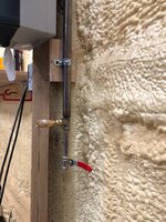
The only component missing is a ball valve that I will add in the vertical riser.

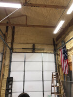
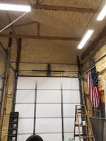
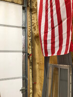
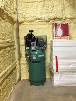
The shop is a 30 X 40 X 14 post frame that I built last year. it is spray foamed as you'll see and otherwise unfinished inside.
The compressor is an 80gal SpeedAire 5HP 1725 RPM rated 17 CFM.
The install is to support my car restoration plan including the occasional sand blasting, blast cabinet, air tools, painting. Quick connect drops and fittings in six places, with one of them specifically piped for higher flow for a sandblast pot and a half-inch QC.
I'm adding a cooler between the pump and tank (after cooler) fashioned from a repurposed hydraulic oil cooler.
Just under the cooler, there's the (relocated) check valve and a drip leg which will get an auto dump valve, with another on the tank drain.
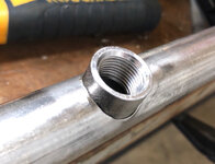
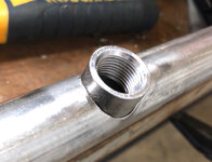
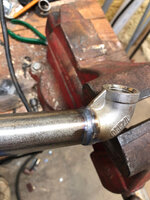
The cooler and the associated piping at the compressor is 3/4 ID copper and 1" ID copper, brazed. From there, the piping is 1" OD 0.083 wall 316L SS and goes vertical to 13'. The tubing is fairly heavy wall but not heavy enough to be threaded. Every connection is either TIG welded to another tube or to a threaded fitting to allow connection to another.
It then runs as a trunk line along the West wall 40' dropping 12" in the process.
At this low end there is a tee, dropping to a drip leg to drain the trunk, and a riser that crosses over to the next bay, dropping to a cross with QCs inside and outside the wall.
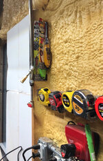
Along the trunk line, there are three topside ports, 180 degree turns down to two drops and the third runs up and over the shop, dropping down along one lift post and also over to the East side workbench area.
It is my intent that the aftercooler will be able to knock most of the water out
and into the dripleg before it gets a chance to get carried up to the trunk line. The tall vertical should help drop some out (back to the first drip leg).
The trunk line is set up to drop any water to the drip leg at the South end of its run. Hopefully none of the topside ports will get any water, but every QC drop has a drain just to be sure.
The copper piping at the compressor is not pretty, but every effort was made to drop moisture into the drip leg and not into the tank or line. I relocated the check from the tank and installed it before the drip leg, before the tee.
The main reason I went this way (rather than just connecting to the port on the other side of the compressor) is to make the connection at this 3/4 port rather than the provided 1/2" on the other side.
Pictures to follow... they are on my phone; I'll upload them today
08b6e0034775d0a6dd42f4a7e9aa0c39.jpg
95ed3decd4a96680d817199f1b63dfda.jpg
97ba559f8054060d0e51c4c634d2b1c0.jpg
ad3683dc05e8f68c1d77c58dcd34029f.jpg
32e0b44a128bd68a7d5b0396fc2cec88.jpg
3b3ddcb91c39a72779c7f7f2899ffc8c.jpg
More pics coming....
774361238fe00dee8987cde433162143.jpg
2d889e96551e960def9067f92a25a0d7.jpg
5ad7d532559f0fc2797b287c3d5f0e73.jpg
bcca9a6f957809c5f6dabe26c73d276f.jpg
3773d7386b1f2d61b20ddce680d0f383.jpg
3d6a351f7be07c62f3274757d5855d5d.jpg
d6d30b3f9f83f65bfad2e8d8b3889a01.jpg
e934d9c1efaf4e3c5e84fdf01f93d8a2.jpg
f77c72ab34506716b6c88d30e0653748.jpg
bc3c315d87e1c7d010d670922707972b.jpg
1739543505a864b6ce4f82b854a10d7a.jpg
5d83fba0f603b571e60c24c88bf890bd.jpg
07c8dcdb8c92a6823895f7215ce14ba6.jpg
dbd4d97db1f4b7d41ba52389167c14fd.jpg
6788d1acb2d3bb3c3b0b97c5f043b502.jpg
597409beea7929ebbf70c4f35a7e2ba5.jpg
e9d08f4c80f5a2fca222fe8051926cbf.jpg
132d27816db0a8455e849a045642f696.jpg
401ea2358a6fbfa50ab5bf70f6a21c8d.jpg
c16997dee31c238fe1ab07dab406cce4.jpg
77e5bcc05c703638e940c9f0d5beb6e4.jpg
d5a88c38bbb13447e04474d238890c90.jpg
49fb5410f052d83a87b535690d141223.jpg
cd202e7ef0e823680b9047d0080a6a73.jpg
40daa2b8b1f3828556437060df86eaba.jpg
5886bf704eb599800a4fb378408a68ef.jpg
66de43bb130dcda4969a3175bd2f5a69.jpg
7e39ed2863a6d08764fc6c5f8f6f9761.jpg

At this point the piping is operational; the temp difference top and bottom of the cooler is huge. I'll have to get a good thermometer to check it but suffice it to say that its huge.
Remaining detail: I am going to cut in a ball valve in the riser from the compressor tee; I'm going to replace all the pipe straps with proper clips; I will fabricate a bracket to clamp the drop to the two-post lift and a bracket to provide support to hold the cooler.

EDIT FOR NEW READERS OF THIS THREAD: All of this copper piping just below the after cooler was tossed out because it was too ugly, too cramped (and I just didn’t like it). I replaced it with a new all-stainless redesign. This starts about post #40
 

Attachments

  • 7e39ed2863a6d08764fc6c5f8f6f9761.jpg
    7e39ed2863a6d08764fc6c5f8f6f9761.jpg
    296.1 KB · Views: 1
  • bc3c315d87e1c7d010d670922707972b.jpg
    bc3c315d87e1c7d010d670922707972b.jpg
    233.4 KB · Views: 1
  • f77c72ab34506716b6c88d30e0653748.jpg
    f77c72ab34506716b6c88d30e0653748.jpg
    44.2 KB · Views: 1
  • e934d9c1efaf4e3c5e84fdf01f93d8a2.jpg
    e934d9c1efaf4e3c5e84fdf01f93d8a2.jpg
    331.7 KB · Views: 1
  • d6d30b3f9f83f65bfad2e8d8b3889a01.jpg
    d6d30b3f9f83f65bfad2e8d8b3889a01.jpg
    79.4 KB · Views: 1
  • 3d6a351f7be07c62f3274757d5855d5d.jpg
    3d6a351f7be07c62f3274757d5855d5d.jpg
    409.5 KB · Views: 1
  • 3773d7386b1f2d61b20ddce680d0f383.jpg
    3773d7386b1f2d61b20ddce680d0f383.jpg
    69.4 KB · Views: 1
  • bcca9a6f957809c5f6dabe26c73d276f.jpg
    bcca9a6f957809c5f6dabe26c73d276f.jpg
    531.5 KB · Views: 1
  • 5ad7d532559f0fc2797b287c3d5f0e73.jpg
    5ad7d532559f0fc2797b287c3d5f0e73.jpg
    367.1 KB · Views: 1
  • 2d889e96551e960def9067f92a25a0d7.jpg
    2d889e96551e960def9067f92a25a0d7.jpg
    62.5 KB · Views: 1
  • 774361238fe00dee8987cde433162143.jpg
    774361238fe00dee8987cde433162143.jpg
    401.8 KB · Views: 1
  • 3b3ddcb91c39a72779c7f7f2899ffc8c.jpg
    3b3ddcb91c39a72779c7f7f2899ffc8c.jpg
    388.1 KB · Views: 1
  • 32e0b44a128bd68a7d5b0396fc2cec88.jpg
    32e0b44a128bd68a7d5b0396fc2cec88.jpg
    75 KB · Views: 1
  • ad3683dc05e8f68c1d77c58dcd34029f.jpg
    ad3683dc05e8f68c1d77c58dcd34029f.jpg
    393.1 KB · Views: 1
  • 97ba559f8054060d0e51c4c634d2b1c0.jpg
    97ba559f8054060d0e51c4c634d2b1c0.jpg
    426.6 KB · Views: 1
  • 95ed3decd4a96680d817199f1b63dfda.jpg
    95ed3decd4a96680d817199f1b63dfda.jpg
    377.5 KB · Views: 1
  • 1739543505a864b6ce4f82b854a10d7a.jpg
    1739543505a864b6ce4f82b854a10d7a.jpg
    243 KB · Views: 0
  • 5d83fba0f603b571e60c24c88bf890bd.jpg
    5d83fba0f603b571e60c24c88bf890bd.jpg
    408.9 KB · Views: 0
  • 66de43bb130dcda4969a3175bd2f5a69.jpg
    66de43bb130dcda4969a3175bd2f5a69.jpg
    240.7 KB · Views: 0
  • 5886bf704eb599800a4fb378408a68ef.jpg
    5886bf704eb599800a4fb378408a68ef.jpg
    271.8 KB · Views: 0
  • 40daa2b8b1f3828556437060df86eaba.jpg
    40daa2b8b1f3828556437060df86eaba.jpg
    355.2 KB · Views: 0
  • cd202e7ef0e823680b9047d0080a6a73.jpg
    cd202e7ef0e823680b9047d0080a6a73.jpg
    410 KB · Views: 0
  • 49fb5410f052d83a87b535690d141223.jpg
    49fb5410f052d83a87b535690d141223.jpg
    230 KB · Views: 0
  • d5a88c38bbb13447e04474d238890c90.jpg
    d5a88c38bbb13447e04474d238890c90.jpg
    301.3 KB · Views: 0
  • 77e5bcc05c703638e940c9f0d5beb6e4.jpg
    77e5bcc05c703638e940c9f0d5beb6e4.jpg
    302.1 KB · Views: 0
  • c16997dee31c238fe1ab07dab406cce4.jpg
    c16997dee31c238fe1ab07dab406cce4.jpg
    314.1 KB · Views: 0
  • 401ea2358a6fbfa50ab5bf70f6a21c8d.jpg
    401ea2358a6fbfa50ab5bf70f6a21c8d.jpg
    354.7 KB · Views: 0
  • 132d27816db0a8455e849a045642f696.jpg
    132d27816db0a8455e849a045642f696.jpg
    338.5 KB · Views: 0
  • e9d08f4c80f5a2fca222fe8051926cbf.jpg
    e9d08f4c80f5a2fca222fe8051926cbf.jpg
    358.8 KB · Views: 0
  • 597409beea7929ebbf70c4f35a7e2ba5.jpg
    597409beea7929ebbf70c4f35a7e2ba5.jpg
    396.4 KB · Views: 0
  • 6788d1acb2d3bb3c3b0b97c5f043b502.jpg
    6788d1acb2d3bb3c3b0b97c5f043b502.jpg
    392 KB · Views: 0
  • dbd4d97db1f4b7d41ba52389167c14fd.jpg
    dbd4d97db1f4b7d41ba52389167c14fd.jpg
    334.1 KB · Views: 0
  • 07c8dcdb8c92a6823895f7215ce14ba6.jpg
    07c8dcdb8c92a6823895f7215ce14ba6.jpg
    400.3 KB · Views: 0
  • 08b6e0034775d0a6dd42f4a7e9aa0c39.jpg
    08b6e0034775d0a6dd42f4a7e9aa0c39.jpg
    391.8 KB · Views: 1
Last edited:
To avoid these ads, REGISTER NOW!

LXCam

ALLIANCE MEMBER
Joined
Apr 23, 2013
Messages
19,372
Location
AZ
Holy **** that was a ton of welding and fit up. Nice job!
 
OP
M

MrSurly

Well-known member
Joined
Jan 15, 2014
Messages
1,671
Location
East Texas
Are you going to get enough air flow with it so close to the wall?

I do wish I had mounted the compressor a bit further away from the wall but I didn't think far enough ahead. I can, if it seem necessary, either drill new anchors to move it OR, I can trim the wall foam insulation back a bit.

At this point it seems pretty effective as is at lowering the temp.
 
OP
M

MrSurly

Well-known member
Joined
Jan 15, 2014
Messages
1,671
Location
East Texas
Hard line from the comp to the distribution? You should have something flexible in there
I've given that some thought and may add a hose later. the way it's piped now, the riser is supported vertically at the top but not anchored otherwise and can 'float' laterally so the horizontal is safe. The vertical axis could give me an issue down the road.
 

May Pop

Well-known member
Joined
Aug 7, 2005
Messages
783
Location
Lake in the hills Il.
Nice job on the whole project. I like the way you teed up as Ive found thats the best for keeping the air dry. Was the stainless donated or bought cheap. Are the fitting a slip on?

Ron
 
Last edited:
OP
M

MrSurly

Well-known member
Joined
Jan 15, 2014
Messages
1,671
Location
East Texas
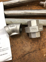
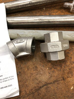
The stainless popped up on CL for $1.00/foot. I had been pricing black iron and copper at way more. None of the fittings are slip-on. Actually none of the fittings are made for the purpose. Most were **** welds but the 1/2 ******* would actually fit inside the tubing with some persuasion. That made those easier to weld for sure.
Noteworthy: The tees and ******* etc for welding to this all had to be stainless of course. Much to my surprise, going to an industrial metal supplier locally, I was able to buy the SS fittings for *HALF* what Lowes was charging for *Galvanized*
 

May Pop

Well-known member
Joined
Aug 7, 2005
Messages
783
Location
Lake in the hills Il.
The big box store charge more than McMasterCarr charges for black fitting also.
McMasterCarr is X3 for SS fitting over black. You got a great deal on all the material.
 

kbs2244

Well-known member
Joined
Nov 11, 2006
Messages
14,065
That is very well done.

My only comment would be, as said, flex between the compressor and the piping, and a 45 vs 90 degree for the hose hook ups.
It just lessens the stress on the hose.
 

pattenp

Well-known member
Joined
Jun 4, 2008
Messages
10,175
Location
Virginia - USA
I do wish I had mounted the compressor a bit further away from the wall but I didn't think far enough ahead. I can, if it seem necessary, either drill new anchors to move it OR, I can trim the wall foam insulation back a bit.

At this point it seems pretty effective as is at lowering the temp.

Too close to wall. Should be around 18" to 24" away from wall for good air circulation from air to cool compressor head. Read the install manual.
 
OP
M

MrSurly

Well-known member
Joined
Jan 15, 2014
Messages
1,671
Location
East Texas
Too close to wall. Should be around 18" to 24" away from wall for good air circulation from air to cool compressor head. Read the install manual.

I actually looked that up, for grins. The manual calls for 12" not twice that but it actually only has about *half that. I may consider moving out a bit *IF* there proves to be an issue with cooling. It is truly much more likely that I will install a simple electric fan (pressure switched) adjacent to ensure adequate air.
 
To avoid these ads, REGISTER NOW!

exranger06

Well-known member
Joined
Aug 9, 2015
Messages
1,686
Location
CT
Keeping the compressor away from the walls is also necessary for servicing. Do you have enough room to change the belt where it is?

Off-topic: I thought it was against building code to have exposed spray foam insulation due to its fire resistance (or lack thereof). Do you plan to cover it up eventually? Ok I'm done criticizing now. The piping looks really good.
 
OP
M

MrSurly

Well-known member
Joined
Jan 15, 2014
Messages
1,671
Location
East Texas
Keeping the compressor away from the walls is also necessary for servicing. Do you have enough room to change the belt where it is?


Yes, as a matter of fact, I noticed that the motor sheave needed to be moved to re-align the belt when I was taking measurements for the cooler. the cage assembly has just enough room for removal. This was the way I planned when installing, of course but in retrospect I wash I'd given it a few more inches.
1427565685a500207c5ec982aae4335e.jpg

17efbbd5af0a3abafad2be3aba5e4601.jpg


Off-topic: I thought it was against building code to have exposed spray foam insulation due to its fire resistance (or lack thereof). Do you plan to cover it up eventually? Ok I'm done criticizing now. The piping looks really good.


The building passed city inspection with no issues. The inspector stated that if it were a *residence* that it would have to be covered by 1/2 Sheetrock or OSB. Because it's a detached garage, he said the covering is not mandated. I don't currently have a plan to cover it but I will likely drywall *some* of it just to create a fab shop area.
 

Attachments

  • 17efbbd5af0a3abafad2be3aba5e4601.jpg
    17efbbd5af0a3abafad2be3aba5e4601.jpg
    707.5 KB · Views: 1
  • 1427565685a500207c5ec982aae4335e.jpg
    1427565685a500207c5ec982aae4335e.jpg
    857.6 KB · Views: 0
Last edited:
OP
M

MrSurly

Well-known member
Joined
Jan 15, 2014
Messages
1,671
Location
East Texas
Following up just to complete the install. I did cut in a cut-oiff valve and also added a somewhat-easier-to-read gauge for my old eyes.
c738769a9af069303e33c426eedaea81.jpg
61d17739d50fa2c6a2a1c275ff9b29cc.jpg
 

Attachments

  • c738769a9af069303e33c426eedaea81.jpg
    c738769a9af069303e33c426eedaea81.jpg
    987.3 KB · Views: 0
  • 61d17739d50fa2c6a2a1c275ff9b29cc.jpg
    61d17739d50fa2c6a2a1c275ff9b29cc.jpg
    974 KB · Views: 0
Last edited:

Firebrick43

Well-known member
Joined
May 12, 2015
Messages
14,419
Location
West central Indiana
What ss rod are you using? Either to much heat,to large of rod, went over a bead a second time, or steel/309L? Normally 308 or my fav tigtectic 680 is bright and shiny with the rainbow colors.

Also way to much heat with the brazing. Oxy torch or tig? Carefull use of silcone bronze can look stack of dimes and silphos brazing shouldn't spread that far.

Nothing looks structurally deficient however.
 
Last edited:
OP
M

MrSurly

Well-known member
Joined
Jan 15, 2014
Messages
1,671
Location
East Texas
Nothing looks structurally deficient however.

Well at least there’s that!

Also way to much heat with the brazing. Oxy torch or tig? Carefull use of silcone bronze can look stack of dimes and silphos brazing shouldn't spread that far.
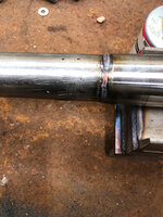
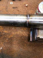
Sil-phos (StaySilv 15); Oxy acet rig. Waaaayyy out of practice!

What ss rod are you using? Either to much heat,to large of rod, went over a bead a second time, or steel/309L? Normally 308 or my fav tigtectic 680 is bright and shiny with the rainbow colors.
Now THIS is a subject I want to explore with someone who knows! If you read the thread, you see that I’m teaching myself, and my instructor is a *******.
I have been *trying* to get the rainbow colors...
watching videos, unable to figure out the exact issue(s).
The last few pics above were not double passes, they were not knowingly cooked though some others were, especially the 3/4 Tee. After a while I finally got in tight enough that I got a few narrow beads, had good puddle control, seemed as good as my best so far, but still turn gray.
If you are up for it I’d like to pick your brain on this.


Sent from my iPhone using Tapatalk
 
OP
M

MrSurly

Well-known member
Joined
Jan 15, 2014
Messages
1,671
Location
East Texas
Here’s what I’m working with:e1e56f4e14c8bf37a055be341744f7c6.jpg
2434a969dfbf881bf5e95e78e3163a03.jpg
9bd8715c7e716b8a3fd4573562f36e76.jpg
316 083 wall
316 1/16 rod
304 fittings
2% Thoriated tungsten
100% Argon
300A Lift TiG machine
No foot control

I don’t know if I’m using the wrong filler, too small a gas lens, too little gas flow...
I have a 5, 6 and a broken size 7 gas
Lens.
I have more and larger “gas lens” ordered in various sizes.

When I watch the you tubers who all create the rainbow beads I see a few differences in method but it doesn’t seem like any of them would be the obvious difference in color.

1. They all are using monster size gas lenses
2. They all are using back purge
3. They all have foot controls (and most have hi-freq start)
4. Positioners used on pipe stuff.

Any of these a glaring “cause” potentiallly?


Sent from my iPhone using Tapatalk
 

Attachments

  • e1e56f4e14c8bf37a055be341744f7c6.jpg
    e1e56f4e14c8bf37a055be341744f7c6.jpg
    1.1 MB · Views: 0
  • 2434a969dfbf881bf5e95e78e3163a03.jpg
    2434a969dfbf881bf5e95e78e3163a03.jpg
    777.9 KB · Views: 0
  • 9bd8715c7e716b8a3fd4573562f36e76.jpg
    9bd8715c7e716b8a3fd4573562f36e76.jpg
    904.1 KB · Views: 0

camaro77

Active member
Joined
May 12, 2018
Messages
29
Location
rhode island
I would tig this all up with prob .045 or 1/16 filler rod SS just pretty much need a rod with a higher # than the material so if you tube is say 304 I would use 308 or 316. def way to hot I would be prob about 70 amps and get a puddle going then pulse with my foot gray is not good need a nice rainbow. I use #7 cup with a gas lense for pretty much everything I do im cheap so I only flow 12 inches of argon when I weld all my stuff.
 

dr_clyde

Well-known member
Joined
Jan 7, 2009
Messages
6,511
Location
Holland, MI
I agree those welds are too hot. What amperage are you running? Remember that heat input is a function of amperage and travel speed, primarily. If you run high amperage, you need to move fast, and vice versa.

The "rainbow" on stainless welds is due to oxidation at specific temperatures. The gray color is too hot. If it crystallizes and makes what looks like sugar in the welds, that is excessively hot. This is mitigated primarily with heat input, but external shielding is also important.

Ideally the weld should be silver, no color at all. Some color is fine with most applications of SS, especially for air lines. It is pretty difficult to avoid oxides on the exterior of a weld without a purge box, trailing shield, or purge chamber. Most of the time there is not a problem with that.

I would personally run that with a #6 gas lens, 1/8" electrode, ( I prefer ceriated, but it doesn't really matter on DC), and I'd use a foot control if I had one. Amperage range between 75 and 125. Since you don't have a foot pedal, I'd set the machine to 90 to start and bump up or down depending on how it goes.

I like a 1/16" rod for general smaller work, since you're welding 316 you should technically be using 316 filler, but for a simple air line, any 300 series will work fine.

Here are some sample welds I did on some .065 wall sanitary tubing. I weld a lot of stainless. IIRC, these were welded at 34 or 35 amps, walking the cup.

These are on the verge of being too hot, but I'm also doing full penetration welds, and the inside is the important bit. The outsides get polished and passivated. These are purged before and during welding.

32911384636_0f3a02a73b_b.jpg


22410463527_528beb767a_b.jpg


22206085724_3783e096f8_b.jpg


22409945407_e3e0b45103_b.jpg
 

dr_clyde

Well-known member
Joined
Jan 7, 2009
Messages
6,511
Location
Holland, MI
I don’t know if I’m using the wrong filler, too small a gas lens, too little gas flow...
I have a 5, 6 and a broken size 7 gas
Lens.
I have more and larger “gas lens” ordered in various sizes.

When I watch the you tubers who all create the rainbow beads I see a few differences in method but it doesn’t seem like any of them would be the obvious difference in color.

1. They all are using monster size gas lenses
2. They all are using back purge
3. They all have foot controls (and most have hi-freq start)
4. Positioners used on pipe stuff.

Any of these a glaring “cause” potentiallly?

Sent from my iPhone using Tapatalk

None of these things make much difference in the hands of an inexperienced welder. Its all technique.

If I could recommend 2 tips for stainless tig, it would be to weld hot enough to move quickly, then move quickly. Then, keep a tight arc. The tighter your arc is, the more intense and focused it is on a smaller point.

Monster gas lenses do help with oxides, but you can get perfectly acceptable welds, even exceptional welds with common gas lenses and cups.

Back purge is required in some situations, where the inside or backside is required to be clean or fully fused. Not required to get nice looking fillet welds on a socket weld, at least on the outside. I purge most if not all thin stainless tube, because it aids in puddle control and penetration.

Foot controls are handy, but I usually do pipe welding without one. I like them for shop and bench work, but position welds are all lift arc with fixed amps.

Positioners are for money making. They save so much time. But they aren't required by any means. Most in field pipework is done all by hand. They only break out the positoners and mechanized welding equipment if there is lots of welding to do and it will save an appreciable amount of time. I have a turntable positoner, and use it when appropriate, but rarely on pipework.
 
OP
M

MrSurly

Well-known member
Joined
Jan 15, 2014
Messages
1,671
Location
East Texas
I would tig this all up with prob .045 or 1/16 filler rod SS just pretty much need a rod with a higher # than the material so if you tube is say 304 I would use 308 or 316. def way to hot I would be prob about 70 amps and get a puddle going then pulse with my foot gray is not good need a nice rainbow. I use #7 cup with a gas lense for pretty much everything I do im cheap so I only flow 12 inches of argon when I weld all my stuff.


The rod is 1/16 316ss
Machine is set on 60a for all of the welds that I’ve done on this. I don’t have a foot pedal, it’s a lift Tig with a little knob on the torch. The knob switches it on/off but I can’t tell that the knob’s range of rotation has any effect on the heat. (I’m not looking up at the box to see)
I tried at 90a at first and man I cooked some stuff! I’ve been guilty of using that busted cup as well, surely that’s not helping.


Sent from my iPhone using Tapatalk
 
Last edited:

dr_clyde

Well-known member
Joined
Jan 7, 2009
Messages
6,511
Location
Holland, MI
The rod is 1/16 316ss
Machine is set on 60a for all of the welds ghost I’ve done on this. I don’t have foot pedal, it’s a lift Tig with a little knob on the torch. The knob switches it on/off but I can’t tell that the knob’s range of rotation has any effect on the heat. (I’m not looking up at the box to see)
I tried at 90a at first and man I cooked some stuff! I’ve been guilty of using that busted cup as well, surely that’s not helping.


Sent from my iPhone using Tapatalk

If you're cooking it at 60 amps you're going too slow. Keep a tight arc, move faster. You may need to bump the amps up to allow the faster movement, but decrease the overall heat.

Its possible your torch has an amperage control on it, but it may be just a gas valve. Post a pic of your torch?
 
Last edited:

dr_clyde

Well-known member
Joined
Jan 7, 2009
Messages
6,511
Location
Holland, MI
I should point out that my welds while done at 35 amps, were done fairly slowly to allow the metal to melt all the way through.

If I was capable of moving faster and doing it in a controlled fashion, I.E. an orbital welder, that same joint would be done at 100 amps.

Amps + travel speed = heat input.
 
OP
M

MrSurly

Well-known member
Joined
Jan 15, 2014
Messages
1,671
Location
East Texas
None of these things make much difference in the hands of an inexperienced welder. Its all technique.


If I could recommend 2 tips for stainless tig, it would be to weld hot enough to move quickly, then move quickly. Then, keep a tight arc. The tighter your arc is, the more intense and focused it is on a smaller point.


Monster gas lenses do help with oxides, but you can get perfectly acceptable welds, even exceptional welds with common gas lenses and cups.


Back purge is required in some situations, where the inside or backside is required to be clean or fully fused. Not required to get nice looking fillet welds on a socket weld, at least on the outside. I purge most if not all thin stainless tube, because it aids in puddle control and penetration.


Foot controls are handy, but I usually do pipe welding without one. I like them for shop and bench work, but position welds are all lift arc with fixed amps.


Positioners are for money making. They save so much time. But they aren't required by any means. Most in field pipework is done all by hand. They only break out the positoners and mechanized welding equipment if there is lots of welding to do and it will save an appreciable amount of time. I have a turntable positoner, and use it when appropriate, but rarely on pipework.


This is the kind of info I need. Those are beautiful welds! At first I watched all the videos and am blown away by some of you guys. This “Kanekid welding” guy is welding incredibly thin stainless (looks like a Thermos bottle) making rainbows that would put My Little Pony in the stable and the machines showing 90amps when he’s doing it!

I have another piece out there, much thicker stuff (.160”) and I need a **** weld. Because it’s thicker and fit tight, and I’m ‘cheating’ I practiced autogenous welding on it at 90a, rolling it on the table (my positioner).
At first I got rainbow
3a67a7868660954383195762dcea591f.jpg
Then slowed just a little and went gray
1f6fddc96ef6a4de91f253a1c1b25cf4.jpg
So then I started experimenting on this piece trying a weave, circles to see if I could make a broader weld without filler just to learn. I learned right away that *this is how you overheat a weld zone!
be3210623ab23771370892ac0495d2b6.jpg
6112439e64836bf6fe2ba4f62aef2315.jpg
b322d5fada196b87e86d8457708215ca.jpg
This is helping, guys. I’m learning something. First I shouldn’t have started my training on thin stuff(!)
I think that I’m learning that running a little hotter (if I can nail the travel speed) I could do better... right?
Importantly, I found that it NOT because I have the wrong rod, the wrong gas, the wrong tungsten, the wrong machine.
What I’ve got IS capable and just waiting for me to catch up


Sent from my iPhone using Tapatalk
 

Attachments

  • b322d5fada196b87e86d8457708215ca.jpg
    b322d5fada196b87e86d8457708215ca.jpg
    850.3 KB · Views: 0
  • 1f6fddc96ef6a4de91f253a1c1b25cf4.jpg
    1f6fddc96ef6a4de91f253a1c1b25cf4.jpg
    923.2 KB · Views: 0
  • 3a67a7868660954383195762dcea591f.jpg
    3a67a7868660954383195762dcea591f.jpg
    859.7 KB · Views: 0
  • be3210623ab23771370892ac0495d2b6.jpg
    be3210623ab23771370892ac0495d2b6.jpg
    902.4 KB · Views: 0
  • 6112439e64836bf6fe2ba4f62aef2315.jpg
    6112439e64836bf6fe2ba4f62aef2315.jpg
    932.8 KB · Views: 0
OP
M

MrSurly

Well-known member
Joined
Jan 15, 2014
Messages
1,671
Location
East Texas
Its possible your torch has an amperage control on it, but it may be just a gas valve. Post a pic of your torch?


Pic
Has off and 1-10
I cannot discern any effect on the power, but someone familiar would, I’m sure.
d6570be58f9790e75df8028ff414b224.jpg
63d9bf08cfbb8f68ee970cd73cdc0ac6.jpg


Sent from my iPhone using Tapatalk
 

Attachments

  • 63d9bf08cfbb8f68ee970cd73cdc0ac6.jpg
    63d9bf08cfbb8f68ee970cd73cdc0ac6.jpg
    920.3 KB · Views: 0
  • d6570be58f9790e75df8028ff414b224.jpg
    d6570be58f9790e75df8028ff414b224.jpg
    780.2 KB · Views: 0
OP
M

MrSurly

Well-known member
Joined
Jan 15, 2014
Messages
1,671
Location
East Texas
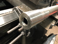
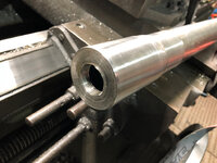
I like this thicker stuff!
These pieces are from different scrap stuff from work, repurposed pieces, much of it ugly... but all of it priced right!
dcbe45ff7e7e267edf60f27cdd449d7b.jpg
The ugly will be turned off of the plug piece.

After cleanup
7dfc3cfb382b1ffad8ac43267253aa6c.jpg
6631be6e01f6785098ce1f3534eed9e7.jpg
 

Attachments

  • 7dfc3cfb382b1ffad8ac43267253aa6c.jpg
    7dfc3cfb382b1ffad8ac43267253aa6c.jpg
    708.1 KB · Views: 0
  • 6631be6e01f6785098ce1f3534eed9e7.jpg
    6631be6e01f6785098ce1f3534eed9e7.jpg
    674.8 KB · Views: 0
  • dcbe45ff7e7e267edf60f27cdd449d7b.jpg
    dcbe45ff7e7e267edf60f27cdd449d7b.jpg
    883.4 KB · Views: 1
Last edited:
To avoid these ads, REGISTER NOW!
Top Bottom