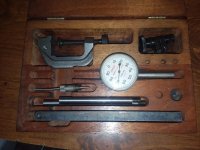
Here is Starrett's version of that indicator. The illustration shows it assembled with the swivel joint on the tool post holder, but using the c-clamp holder works the same way.
http://www.starrett.com/metrology/product-detail/196A1Z
EDIT: Here is a video that shows a little more about how it works. There are several other videos shown that will help you understand it better.
You can hold the indicator stem with a conventional magnetic base, or a flex magnetic base as well.
Looks like op's setup is slightly different than the linked Starrett. It appears the Ames doesn't have the slit as leg17 mentioned. Now, I have never had or used an Ames indicator- my experience comes from using Starrett and Lufkin kits, both of which came with the slit clamps. The way the rod protrudes into the other bore made me think of a cam-style clamp like Lufkin used on their micrometers with a spindle lock lever (Not the lock ring, those are a different way of accomplishing same thing). However if everything is uniform diameter, this goes out the window.
Thinking about this more, does swapping the clamp end to end have any effect? It's possible it's backwards or something else is going on, like rods are slightly different diameters, which a clamp flip should remedy, but isn't guaranteed. Indicator snugs and rods shouldn't be this challenging to figure out, usually the only obstacle is finding rods and clamps that are compatible size-wise, although kits usually eliminate that possibility. Also possible there is a slit or bushing or other method for tightening I just can't see.
Another guess is that one, or some of the accessories aren't original to the set, or parts are missing. In my experience when these indicator sets are shop-owned, the snug, indicator itself, and the c-clamp are usually the first pieces to wind up growing legs and disappearing, in that order. Some ham-fists have been known to over-tighten the knurled finger wheel, usually with pliers, which can result in the more fragile pieces breaking, which then results in shop sets being cannibalized for parts.
Having multiple snugs is sometimes the only way to Rube Goldberg together a solution for an odd setup, and those snugs can be pricy when purchased individually. I remember one previous employer had such a problem with the shop Starretts going MIA, he used to order spare snugs 10 at a time and kept them locked away in the tool crib.
I have a feeling there also may be a missing outer sleeve somewhere in that setup, but again...with no experience on an Ames indicator, these are just guesses.
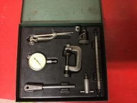
Here is a pic of my Lufkin set, which is similar to Starrett. I bought this set for $20 because the indicator was gummed up from machine coolant, to the point it would only return sluggishly halfway back to zero without assistance.
$20 is about what a snug itself costs new from Starrett, I figured why not give it a try to salvage the Lufkin...worst case, indicator is junk or needs professionally repaired, accessories worth more than $20. A few squirts of CRC QD aerosol electronics cleaner, applied over a few days to the innards, along with gentle cycling, solved this problem (trick I learned from an old timer, he referred to it as 'gage repair facility in a can'
http://www.crcindustries.com/products/qd-174-electronic-cleaner-11-wt-oz-05103.html , I personally have used this on many indicators with very good results). I should point out here NEVER attempt to clean an indicator with an air blow gun, the tiny jewels don't like that, and can shatter and fall out of the assembly, causing all kinds of fun problems.
Point being, if you can find other indicator sets with accessories compatible to yours on the cheap, might as well pick them up. Never hurts to have more.
Good luck with it, op. I'm still scratching my head.


 . I do have a project that needs it tho ( measuring cam lift) but the pictures are really just to show it put together and the piece I can’t figure out. It’s the arm/stem like you describe doesn’t fit as far a I can tell.