To avoid these ads, REGISTER NOW!

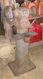
An old friend found - Baldor 8107W

fletcher969

Active member
Joined
Dec 16, 2016
Messages
34
Location
Southern IL
Hi everyone.

To make a long and involved story short, a neighbor of my father's had several grinders scattered around in a couple of shops on his property, but one caught my attention one day a few years ago as he and I were getting acquainted while making some rounds around his place. I made a comment about it looking exactly like a very well-used version of one I used to use when I was a teen working for my dad back in the '70s, missing right side guard and all, whereupon he told me my father had sold it to him over a decade ago. It was the same grinder! I thought it was sold along with Dad's business at the end of the '70s, so I was pleasantly surprised. Dad has since passed away, which has prompted me to remember that grinder on several occasions, so 3 weeks ago I decided to call up Dad's old neighbor to see if he would give me right of first refusal if he ever decided to sell it. He told me it quit running a couple of years ago, and I could have it if I dropped by and picked it up. I'm a bit sentimental, and I'd spent several years after school and on weekends with that thing, so I didn't hesitate, not knowing if it was salvageable or not. It didn't matter, but I figured I was in the market for a decent grinder anyway, and it might accidentally be a decent pick. I have a knack for fixing things others give up on anyway, so all the better.

When I got it home, I plugged it in and flipped its switch. To my surprise, it wasn't completely dead like I had expected, but instead it hummed and spun backwards (wired in reverse?) very slowly around 60-80 RPMs, and it would never wind up to full speed. No amount of manually spinning it in either direction, before or after power was applied, resulted in it "catching" and spinning up to full speed. From what I've read in the various forums -- mostly on this site -- it's likely a capacitor failure. Regardless, I've decided this grinder is well worth whatever effort will be required to restore it (sans the guard and side cover on the right side), so that's my plan.

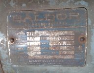
I gathered the information off the nameplate (which is still hard to read), and here's what it indicates:

Baldor
Cat No: 8107W
HP: 3/4
Volts: 115/230
Phase: 1
Cycle: 60
RPM: 1725
Amps: 6.6/3.3
Frame: 524C (???)
Serial: 1070
spec: G8-1-11

The information on the nameplate seems contradictory. All indications on Baldor's site are that this thing should be an 8100W, not an 8107W (1725/1800 vs 3450/3600 RPMs respectiively). Has Baldor changed it model numbering since 1970? If not, that could be an issue given Baldor also indicates each model uses a different capacitor (at least with the modern versions). Also, the 8107W -- the newer model at least -- has a relay, whereas the 8100W does not. Nevertheless, I hope once I open it up I'll be able to compare what I have with the information available to me, and proceed accordingly. It also indicates a Spec# of G8-1-11 for which I can find nothing online except for one Google link where another guy describes his 8107W having that Spec number. I'd be interested in whatever information anyone can confirm or may contribute regarding this grinder.

Before I sign off on this first post, I'm curious what color this model Baldor sported when it was new? It appears to be of the gray variety (versus Vista Green), and I remember it being gray as a kid. I've read where Battleship Gray would be close enough, but I'd like to get something spot on if practical.

Anyway, I've provided a couple of pics. Winter's definitely here, and I don't have adequate floorspace I can heat in which to work on it daily, so I'm not sure how long it will take to complete the restoration, but I'll be sure to post pics of my progress, and inquire within as needed.
 

Attachments
  • IMG_20161215_160637097 resize.jpg
    IMG_20161215_160637097 resize.jpg
    95.7 KB · Views: 396
  • IMG_20161215_160700737 resize.jpg
    IMG_20161215_160700737 resize.jpg
    134.2 KB · Views: 212
Last edited:
To avoid these ads, REGISTER NOW!

Plombob

Well-known member
Joined
Oct 19, 2008
Messages
4,167
Location
Tennessee
Welcome to the board! Good for you for rescuing an old Baldor. I'm interested to learn what causes the malfunction.
 

Provincial

Well-known member
Joined
Sep 21, 2011
Messages
6,882
Location
Near Salem, OR
Since it is a dual voltage motor, check the wiring at the motor to see if someone wired it for 230V and put a 115V plug on the cord.

Nice grinder! It is nice to have such a nice piece to link to your father.
 

bluebolt

Well-known member
Joined
Dec 28, 2008
Messages
5,462
Location
Benton LA
Welcome and great story! The base is killer on that grinder good luck with getting it working properly.
 

chrispyny

Well-known member
Joined
Nov 7, 2013
Messages
467
Location
albany, ny
Looks a little worse than mine when i did a restoration on mine. What you have there, if purchased retail now, would probably cost a little more than $2,000. You are now obligated to restore that to perfect condition. Trust me, it's worth it. To see the water pot cast into the base is quite rare. Must be a very early baldor grinder.
 

Roberts210

Well-known member
Joined
Dec 21, 2015
Messages
3,177
Location
Missouri
Congrats on saving your dad's grinder. If you brush up on electric motors--there are lots of places on the web to do so--you might be able to diagnose and fix the problem yourself. It sounds like it is mis-wired somehow--it doesn't sound like it's dead. I used to get my motors rebuilt at an elec. shop but finally learned how to do them myself. It ain't rocket science.
 
OP
F

fletcher969

Active member
Joined
Dec 16, 2016
Messages
34
Location
Southern IL
Thanks for the responses, guys. Yeah, being my father's grinder, and one I used to use back in the day makes it a great find. That I picked it up for free makes it spectacular. If not for that spontaneous tour around my dad's neighbor's place a few years ago, I'd never have known it was available or still existed at all, and it likely would have ended up in a junk pile.

Provincial & Roberts210 - I can't imagine it's wired incorrectly as it appears not to have been opened up for decades, and it was running off a 110 circuit up until a couple of years ago, but I'll be sure to look it over when I open it up.

jabberwoki - good idea lookig on Craigslist for the guards. It's a long shot, but I'll keep an eye out. As it is, without the right side guards, etc., it's as it was when I used it 4 decades ago, but I would like to complete it just because that's how I am; however, Baldor's prices for those items are pretty close to prohibitive for me at this juncture. :)

chrispyny - the tray and water pot aren't cast into the base. There are 2 screws on which the tray hangs, and the water pot slips into a hole made for it in the tray. You mentioned that it must be an early Baldor. I was told the serial number indicated the year of production, no? Going on that, I assumed mine was manufactured in 1970. If anyone can enlighten me on the year of manufacture based on the information above, I'm all ears!

454ragtop - that link takes me to OWWM, but the page indicates I must register to view it? I may do so anyway as it looks like an interesting site, but right now I can't see whatever it is you might have hoped. Thanks nevertheless.

Again, thanks guys.
 

6PTsocket

Well-known member
Joined
Mar 12, 2014
Messages
4,593
Welcome and great story! The base is killer on that grinder good luck with getting it working properly.
That is genuine Baldor base. I wish I had one. They are pricey. They have not changed; it is just like a new one.

Sent from my SM-G900V using Tapatalk
 

6PTsocket

Well-known member
Joined
Mar 12, 2014
Messages
4,593
A lot of 120/240 motors are also reversable The low speed sounds like you are wired for 220, as another poster suggested. The humming and inability to self start sounds like a bad capacitor or bad centrifugal start switch inside the motor. The running backward is controlled by the same,wires that control the speed. There are two run windings in the motor. They are wired in series for 220 and in parallel for 120. reversing the connections on one of the windings will reverse the motor run direction. It sounds like somebody was messing aound in the terminal box. The voltage and run info should be on the plate. On a grinder they would probably not mention reverse but make sure to follow the 120 wiring instructions exactly and pair the right wires together I would bet that in an attempt to fix the start problem somebody managed to wire the motor for 220 in the wrong direction. If you find the wires wrong, fix them and see if a push won't get it going this time. One thing at a time.

Sent from my SM-G900V using Tapatalk
 
OP
F

fletcher969

Active member
Joined
Dec 16, 2016
Messages
34
Location
Southern IL
Thanks for the wiring tips. They'll come in handy later as I have plenty of different trade skills, but lack sorely in the electrical area where my knowledge is rudimentary. You mentioned wiring instructions (diagram/schematic?) to follow. Where are those found? Somewhere underneath or inside the grinder?

A lot of 120/240 motors are also reversable The low speed sounds like you are wired for 220, as another poster suggested. The humming and inability to self start sounds like a bad capacitor or bad centrifugal start switch inside the motor. The running backward is controlled by the same,wires that control the speed. There are two run windings in the motor. They are wired in series for 220 and in parallel for 120. reversing the connections on one of the windings will reverse the motor run direction. It sounds like somebody was messing aound in the terminal box. The voltage and run info should be on the plate. On a grinder they would probably not mention reverse but make sure to follow the 120 wiring instructions exactly and pair the right wires together I would bet that in an attempt to fix the start problem somebody managed to wire the motor for 220 in the wrong direction. If you find the wires wrong, fix them and see if a push won't get it going this time. One thing at a time.

Sent from my SM-G900V using Tapatalk
 

6PTsocket

Well-known member
Joined
Mar 12, 2014
Messages
4,593
They should be on the electrical plate. When you get to it, open the electrical box. See if the wires have number tags. See whatd you have and call Baldor so if they ask questions you will be able to help them . Tell them it hums and runs backward slowly.

Sent from my SM-G900V using Tapatalk
 

6PTsocket

Well-known member
Joined
Mar 12, 2014
Messages
4,593
I did a little research. Unlike motors that have the wiring in a box, Baldor grinders have it in the base. You will have to take it off the pedestal and flip it over. I found the instructions for a similar Baldor grinder with directions for 120 or 220 operation and even reverse. The good news is there is no centrifugal switch so if the windings are not fried you might have to replace the capacitor and or move some wires. The manual lists the wires by color or as T1, T2, T3, etc.marked on the wires. When you get it off the pedestal and flipped over, post again.

Sent from my SM-G900V using Tapatalk
 

454ragtop

Well-known member
Joined
Mar 24, 2008
Messages
5,011
Location
Carver, MA
I was trying to send you to the electrical forum at OWWM.org , think you have to register to view the for sale ads, but pretty sure you can lurk without registering on the rest of the site. That said, registering is free and pretty painless, so no reason to worry about that.
 
OP
F

fletcher969

Active member
Joined
Dec 16, 2016
Messages
34
Location
Southern IL
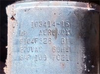
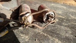
Alright, I had an opportunity to open up the bottom of the grinder. No schematic or wiring instructions therein (unless I'm supposed to dig deeper), so I took a picture of what's underneath it. About all I can make out are a bunch of wires (mostly black) that hook up to the switch, the motor, and to 2 capacitors I believe are connected in parallel. Maybe somebody can make out what's in the picture? One of the capacitors' top is very obviously ballooned, so I'll just start by replacing the capacitors. Both are the same type/value (see pic for the numbers - from what I gather they're 370V 8uF 100 capacitor?). That said, none of the wiring diagrams I viewed in Baldor's product catalog for either the 8100W or the 8107W show 2 capacitors, so I'm at a loss given my lack of knowledge about electrical circuits. If I had a diagram for this model specifically, I can at least mimic it in a practical sense (ex. I wired a complete tractor once using only a wiring diagram).

Anyway, if anybody can make sense of what I photographed, and can explain to me what I have, or if even if it's wired for 110 or 220, I'd be very appreciative.

And for what it's worth, I saw no evidence anybody has ever opened this thing up before.

Thanks.
 

Attachments

  • IMG_20161219_152514685_HDR crop.jpg
    IMG_20161219_152514685_HDR crop.jpg
    149.5 KB · Views: 102
  • IMG_20161219_152159603_HDR.jpg
    IMG_20161219_152159603_HDR.jpg
    156.3 KB · Views: 139

6PTsocket

Well-known member
Joined
Mar 12, 2014
Messages
4,593
OK. You may or may not be right about the capacitors. Some motors have a start capacitor and a run capacitor or as you said they may be in parallel. The stuff I saw on line was all you were supposed to see. The instructions I saw said that the wires would be marked with indicators like T1, T2, etc. It might be on a tag or printed repeatedly along the wires. They said the wires might be optionally color coded as well but not just depend on color coding. There is no instruction plate. If the terminals on the capacitors are in parallel, it would be a pair of wires between them. Lets call it terninal 1 to terminal 1 and terminal 2 to terminal 2. Then there should be a wire leading away from the 1's and another wire leading away from the 2's. If there are more than 2 wires leadng away from the capacitors they are not in parallel. The important numbers in the capacitor are 8ufd and 370 volts AC Forget the 100. Baldor is very much alive and well Give them the model number and ask for an owners manual or at least the page with the wiring diagram. Capacitors in parallel add up. 8+8=16 ufd or mfd. That is not actually a u but the Greek letter mu for micro. Sometimes they use an m for micro. If they are in parallel one 16 ufd at 370 volts would work if it physically fit under there.. Remember they may have separate jobs. I cannot see well enough. In any case I would replace them. All that was supposed to be under there was a capacitor or two and the switch and some wires.


Sent from my SM-G900V using Tapatalk
 

Roberts210

Well-known member
Joined
Dec 21, 2015
Messages
3,177
Location
Missouri
It looks like some of the wires have metal tags affixed. Pay attention to what is stamped on the tags and how they are connected to each other and post what you find out.
 
To avoid these ads, REGISTER NOW!
OP
F

fletcher969

Active member
Joined
Dec 16, 2016
Messages
34
Location
Southern IL
I called Baldor in St. Louis this morning. The guy to whom I spoke seemed quite knowledgeable about their product line both new and older, but when I gave him the nameplate information off my grinder, he was stumped, and the Spec Number isn't one he could find in the information available to him. I sent him several pictures and the information I have, and he's promised to follow up with some people in AR to see what they can drum up for me.

6PTsocket - Despite my ignorance of electrical anything, I was aware of the u=mico, but I do appreciate your eagerness to educate me in an area where it's sorely needed (edit: I hope to learn far more, so keep it up). That said, there are only 2 wires leading away from the 2nd capacitor leading to the motor (so it's a parallel connection, right?). There appear to be 2 sets of 3 wires connected to each other leading back from the motor. I'll check later and make a make a more detailed connection "diagram" of my own, and report.

Roberts210 - I saw those tags while looking at one of my pictures yesterday, but I've not had a chance to look things over. I'll do so first chance I have, and report back.

I do have a question. 8uF 370V caps are difficult to find, whereas 7.5uF and 10uF are easily found (at least with Mouser and Aerovox caps). I understand at the basic level that the uF rating is the capacitance of the cap, and that voltage is the limit of volts the cap can accept without damage. I've read where I can use a higher voltage cap if I want, but that uF ratings need to be +/1 10% or so (or exact on timing and other sensitive circuits). Should I "downgrade" the uF of my caps to 7.5uF or can or should I "upgrade" the caps to 10uF?

Thanks.
 
Last edited:
OP
F

fletcher969

Active member
Joined
Dec 16, 2016
Messages
34
Location
Southern IL
The Baldor rep contacted me to send him a better picture of the nameplate, so I cleaned it and sent him another picture. After doing so, I noticed there are a couple of other numbers on it near the right side. Do they mean anything? As best as I can determine they are:

LR9438
G0?37 (the first character could be 6, and the 4th character could be a B?, the unknown character could be an I or a 1?)

Here's a pic.
 

Attachments

  • IMG_20161220_113743281_HDR.jpg
    IMG_20161220_113743281_HDR.jpg
    156.5 KB · Views: 94

zak77

Well-known member
Joined
Sep 18, 2014
Messages
1,360
Location
Monson, MA
I have the same grinder except mine might be a 1/2hp but same base and i still have the guards, at least on one side if i remember right. It sure is a work horse.
 

6PTsocket

Well-known member
Joined
Mar 12, 2014
Messages
4,593
7.5ufd should be fine. Make absolutely certain that the voltage rating is quick disconnect tabs on top. Most capacitors of this size are polarized with + and- terminals for DC use. I am very familiar with those places but I always thought of them as electronics distributors and would have never thought of them for electrical supplies. I would have thought of a motor supply or an HVAC supply or an electrical distributor but it sounds like you found the right part. I think you have gotten all I can decipher from the motor plate. I am still not clear about how those capacitors are wired in. Lets try it this way. If you were to cut just 2 wires would it completely separate both capacitors from the grinder? I didn't mean to sound too preachy but I just wanted to point out that that a replacement might be marked mfd and that it is the same as ufd. I recocognize that Aerovox brand name, an old American cap manufacturer. I looked, there is still some made in USA out there; most aren't. If it is the cap(s) and it probably is, you won't have to dig any further and read wire markers.

Sent from my SM-G900V using Tapatalk
 

6PTsocket

Well-known member
Joined
Mar 12, 2014
Messages
4,593
Somehow a chunk of my post was deleted so it sounds incoherent. I started to say for you to make sure that it is an AC capacitor for motor service. I believe you have a motor cap there.

Sent from my SM-G900V using Tapatalk
 
OP
F

fletcher969

Active member
Joined
Dec 16, 2016
Messages
34
Location
Southern IL
Ok, yeah. That quick connect and voltage statement confused me. :) I'm assuming you meant to say that the voltage rating on capacitors has to be at or higher than what's already in there. If that's what you meant, I was aware of that. The same for the quick connects as that's what my current capacitors are. Capacitors for motor service? Are you talking about run capacitors vs. start capacitors, or something completely different?

Alright, I was incorrect about the wiring in my previous post. Here's what I observed the last time I looked them over:

  • The 2 capacitors are connected such that if I orient them exactly the same, with the connectors and the solder spot exactly the same, 2 wires connect each identical quick connect posts (or what I perceive as + to + , and - to - or the same way I would if I were connecting 2 tractor batteries in parallel (see attached picture).
  • On the second capacitor (which inline is nearer to the motor), there are 2 additional wires connected to the second set of terminals which then lead into the motor housing (after passing through connector caps - you should be able to see them in the picture). And to answer your question, yes, if I were to cut those 2 wires, it would completely disconnect the 2 capacitors from the motor (whereupon I would have 2 capacitors connected to each other, and I could toss them aside completely).
  • From the motor housing there are 2 sets of 2 wires coming out, each wire in each set connected via a connector cap. One set of wires is marked 1 and 3, the other set of wires is marked 2 and 4. Each connector cap has an additional/3rd wire that goes to the switch representing wire sets 1/3 and 2/4. From what I think I'm learning about motors, this would be a 110V parallel winding configuration, right?
  • The input power feed is grounded to the housing with a green wire, and the other 2 wires lead to the switch.

So, from what I can gather, the caps are connected in parallel as run caps (I'm assuming since only 2 wires/1 circuit leading away from the caps that I don't have a centrifugal switch or its corresponding circuit inside), the windings are connected in parallel, therefore wired correctly for 110V. By all means, correct me if I'm wrong.

7.5ufd should be fine. Make absolutely certain that the voltage rating is quick disconnect tabs on top. Most capacitors of this size are polarized with + and- terminals for DC use. I am very familiar with those places but I always thought of them as electronics distributors and would have never thought of them for electrical supplies. I would have thought of a motor supply or an HVAC supply or an electrical distributor but it sounds like you found the right part. I think you have gotten all I can decipher from the motor plate. I am still not clear about how those capacitors are wired in. Lets try it this way. If you were to cut just 2 wires would it completely separate both capacitors from the grinder? I didn't mean to sound too preachy but I just wanted to point out that that a replacement might be marked mfd and that it is the same as ufd. I recocognize that Aerovox brand name, an old American cap manufacturer. I looked, there is still some made in USA out there; most aren't. If it is the cap(s) and it probably is, you won't have to dig any further and read wire markers.

Somehow a chunk of my post was deleted so it sounds incoherent. I started to say for you to make sure that it is an AC capacitor for motor service. I believe you have a motor cap there.

Sent from my SM-G900V using Tapatalk
 

Attachments

  • IMG_20161220_135657465.jpg
    IMG_20161220_135657465.jpg
    156 KB · Views: 89

6PTsocket

Well-known member
Joined
Mar 12, 2014
Messages
4,593
THAT is what I wanted to see. They are in parallel. There is no polarity on AC capacitors, no+ or -, the terminals are interchangable. Maybe thay were replaced before and they didn't have a 16 or Baldor had a lot of 8ufd's in stock. Put a single 15 or 16 in there. As I said before, if you can cut 2 wires to completely separate both caps from the grinder, they are in parallel. Any other arangement would take more wires. Check the dimensions of what you buy to make sure it will fit. I don't see a problem. I hope nothing else is wrong but you should be good. I guess you never mentioned the 2 caps to the guy at Baldor.

Sent from my SM-G900V using Tapatalk
 

6PTsocket

Well-known member
Joined
Mar 12, 2014
Messages
4,593
THAT is what I wanted to see. They are in parallel. There is no polarity on AC capacitors, no+ or -, the terminals are interchangable. Maybe thay were replaced before and they didn't have a 16 or Baldor had a lot of 8ufd's in stock. Put a single 15 or 16 in there. As I said before, if you can cut 2 wires to completely separate both caps from the grinder, they are in parallel. Any other arangement would take more wires. Check the dimensions of what you buy to make sure it will fit. I don't see a problem. I hope nothing else is wrong but you should be good. I guess you never mentioned the 2 caps to the guy at Baldor.

Sent from my SM-G900V using Tapatalk
If You like Mouser the part number is
871-B3233216-156J80. It even has an 8mm screw stud on the end for mounting. An L bracket should bring you to the old side bracket mounting hole. It is rated 15ufd 460 volts.

Sent from my SM-G900V using Tapatalk
 

6PTsocket

Well-known member
Joined
Mar 12, 2014
Messages
4,593
If You like Mouser the part number is
871-B3233216-156J80. It even has an 8mm screw stud on the end for mounting. An L bracket should bring you to the old side bracket mounting hole. It is rated 15ufd 460 volts.

Sent from my SM-G900V using Tapatalk
Check the dimensions to make sure it will fit. I am pretty sure it will

Sent from my SM-G900V using Tapatalk
 
OP
F

fletcher969

Active member
Joined
Dec 16, 2016
Messages
34
Location
Southern IL
Actually, I did mention the 2 capacitors to the guy at Baldor. He has since written back, and he sent me an engineer's drawing from 1966 that indicates 2 different capacitor configurations were available for my unit starting in 1968 when the 2 capacitor configuration and corresponding bracket were added. Prior to that, I'm assuming only the single 16uF capacitor configuration was manufactured. Actually there was a 3rd configuration where a 12uF capacitor was indicated, but I have no clue how that was/could be used. He also sent me the applicable wiring diagram, and it's the same one they use for the modern 8100W.

You preempted my next question -- Could I purchase a single 15uF-16uF 370V (or higher V) capacitor. Good to know that's an option so long as I can secure it with a bracket. I do have a question regarding the higher voltage capacitor. In a practical sense, is there a benefit to going to 400+ volts versus 370V?

Thanks for the capacitor reference, but (and here's my ignorance cropping up) that's a film capacitor. Mine are oil filled, and the wiring diagram calls for oil filled. Am I to assume -- uF/V specs aside -- that the internal composition isn't so important as the capacitor's dimensions, connector type, and operating temperature range? Also, my bracket screw is centered square in the middle of my bottom plate, so I'll have to do as you suggested anyway, and make sure it would fit with its end in the center of the plate. Then again, it wouldn't take much to drill another hole where I need to attach the bracket. Duh! :)


THAT is what I wanted to see. They are in parallel. There is no polarity on AC capacitors, no+ or -, the terminals are interchangable. Maybe thay were replaced before and they didn't have a 16 or Baldor had a lot of 8ufd's in stock. Put a single 15 or 16 in there. As I said before, if you can cut 2 wires to completely separate both caps from the grinder, they are in parallel. Any other arangement would take more wires. Check the dimensions of what you buy to make sure it will fit. I don't see a problem. I hope nothing else is wrong but you should be good. I guess you never mentioned the 2 caps to the guy at Baldor.

Sent from my SM-G900V using Tapatalk
 

6PTsocket

Well-known member
Joined
Mar 12, 2014
Messages
4,593
Actually, I did mention the 2 capacitors to the guy at Baldor. He has since written back, and he sent me an engineer's drawing from 1966 that indicates 2 different capacitor configurations were available for my unit starting in 1968 when the 2 capacitor configuration and corresponding bracket were added. Prior to that, I'm assuming only the single 16uF capacitor configuration was manufactured. Actually there was a 3rd configuration where a 12uF capacitor was indicated, but I have no clue how that was/could be used. He also sent me the applicable wiring diagram, and it's the same one they use for the modern 8100W.

You preempted my next question -- Could I purchase a single 15uF-16uF 370V (or higher V) capacitor. Good to know that's an option so long as I can secure it with a bracket. I do have a question regarding the higher voltage capacitor. In a practical sense, is there a benefit to going to 400+ volts versus 370V?

Thanks for the capacitor reference, but (and here's my ignorance cropping up) that's a film capacitor. Mine are oil filled, and the wiring diagram calls for oil filled. Am I to assume -- uF/V specs aside -- that the internal composition isn't so important as the capacitor's dimensions, connector type, and operating temperature range? Also, my bracket screw is centered square in the middle of my bottom plate, so I'll have to do as you suggested anyway, and make sure it would fit with its end in the center of the plate. Then again, it wouldn't take much to drill another hole where I need to attach the bracket. Duh! :)
Newer technology. It says on the drawing "motor run capacitor". That is the important thing because the run capacitor is 100% duty cycle There are probably some oil filled ones if you look Think of the capacitor voltage rating as similar to the PSI rating on a hose You can get away with 200PSI for your application but 300 PSI is stronger. I saw another one rated 370/460, probably to assure those that think they have to match the voltage rating. A higher voltage cap might be a little bigger but if it fits it is good.

Sent from my SM-G900V using Tapatalk
 
OP
F

fletcher969

Active member
Joined
Dec 16, 2016
Messages
34
Location
Southern IL
In practical terms, that means a higher voltage rating should be more durable in a given application, and likely last longer. At least that's why I would purchase a higher PSI hose over one that would only suffice. :) I just figured 370V was likely way more than enough, but given what you added, I'll go with the higher voltage capacitor for a negligible cost.

Ah, I thought the run capacitor designation had more to do with its (typically) lower uF rating than how often/how long it is run. Duration of duty cycle makes sense now when I start putting other facts I've gathered here in the last couple of days.


Newer technology. It says on the drawing "motor run capacitor". That is the important thing because the run capacitor is 100% duty cycle There are probably some oil filled ones if you look Think of the capacitor voltage rating as similar to the PSI rating on a hose You can get away with 200PSI for your application but 300 PSI is stronger. I saw another one rated 370/460, probably to assure those that think they have to match the voltage rating. A higher voltage cap might be a little bigger but if it fits it is good.

Sent from my SM-G900V using Tapatalk
 

6PTsocket

Well-known member
Joined
Mar 12, 2014
Messages
4,593
460 is way overkill especially if you are running on 120. I just didn't see a better choice from Mouser I have even seen good ones for half the price but didn't think you wanted to chase around for a few bucks.I have no idea,what Baldor was doing. Maybe they started with 8,found they needed more and threw in another cap but decided that was too much and went to 12. Twelve is not a popular value today so 15 is a nice compromize. Bottom line: they will all work and you will never notice the difference.

Sent from my SM-G900V using Tapatalk
 

Know Wosad

Banned
Joined
May 15, 2016
Messages
811
Baldor is the king of grinders and buffers. Accept no duplicates. Take it to a Baldor service center and get it sorted out. Its well worth tossing a couple hundred at
 
OP
F

fletcher969

Active member
Joined
Dec 16, 2016
Messages
34
Location
Southern IL
I did a little reading on higher voltage ratings versus lower, and I have no problem with either 370 or 440 volts. I anticipate occasionally running this thing in summer temperatures nearing 100F, so it might do me good to have a little extra "breathing room." I've decided to go with Genteq (formerly GE) as I hear they are about as good as they get. I hear that BHC Aerovox, Epcos, and Panasonic are pretty decent also. A few extra dollars doesn't dissuade me any, so I'd just assume go with what's generally accepted as the best.

And just for clarification, it doesn't matter if I get an oval versus round, or short and stubby versus longer and thinner so long as it will fit, correct?

Also, I also see some Genteq and other big brands that are identified with Lennox or Trane or other OEM applications, but again, so long as the uF, voltage, and all other factors meet the required criteria (edit: and that it's a run capacitor), it doesn't really matter, does it?

460 is way overkill especially if you are running on 120. I just didn't see a better choice from Mouser I have even seen good ones for half the price but didn't think you wanted to chase around for a few bucks.I have no idea,what Baldor was doing. Maybe they started with 8,found they needed more and threw in another cap but decided that was too much and went to 12. Twelve is not a popular value today so 15 is a nice compromize. Bottom line: they will all work and you will never notice the difference.

Sent from my SM-G900V using Tapatalk
 
OP
F

fletcher969

Active member
Joined
Dec 16, 2016
Messages
34
Location
Southern IL
Preliminary indications are it's a capacitor issue, so I'm going to replace the 2 capacitors with a new one, and see if that brings it back to life. If not, I'll consider having it looked over by a professional.


Baldor is the king of grinders and buffers. Accept no duplicates. Take it to a Baldor service center and get it sorted out. Its well worth tossing a couple hundred at
 

6PTsocket

Well-known member
Joined
Mar 12, 2014
Messages
4,593
I've seen that video. With a run cap, more voltage is fine, the capacitance should be close to what the manufacturer called for. Start capacitors are a whole different story, a bigger cap gives a little more starting torque. You have a different type of motor that does not use one; the motor innards are completely different. As for the rest, you are starting to over think it. All those caps are fine. Mount it any way that is sold and the terminals don't short out. It does not matter what industry the ones you saw are marketed to. A run cap is a run cap. You are not in a high heat situation so any of the ones you mentioned will be fine. They can all handle a hot day. The shape only matters if it does not fit. Buy one and enjoy your grinder. Don't start to sound like the guys an these threads that think you can only tighten a nut with a Snap On wrench. There are plenty of good capacitors. I saw some cheap 3 buck, no name ones too. Those I would avoid.

Sent from my SM-G900V using Tapatalk
 

6PTsocket

Well-known member
Joined
Mar 12, 2014
Messages
4,593
Use insulated connectors on the capacitor terminals. They come straight and right angle; use what you need. Thet should fit very snug. Baldor has a video reccomending that you tape the wire nuts after you twist them on.

Sent from my SM-G900V using Tapatalk
 
OP
F

fletcher969

Active member
Joined
Dec 16, 2016
Messages
34
Location
Southern IL
Well, I received the replacement run capacitor (15uf 370V), connected it up, hit the power, and all it did was hum very quietly. No movement whatsoever (same if I tried "jump starting" it by spinning it beforehand). Plugged the old capacitors in place, hit the power, and the motor turns slowly exactly as described in my original post.

Bad replacement capacitor? I'd question if 15uf is enough when 16uf is the original spec, but common sense tells me it should at least spin a lot faster than not at all.

I did figure out that the switch is bad, and stuck in a closed position, so I'll have to replace that eventually. I can set the switch in the on or off position, and current is fed to the motor. My "switch" currently amounts to plugging and unplugging the power cord.
 
Last edited:
To avoid these ads, REGISTER NOW!
Top Bottom