To avoid these ads, REGISTER NOW!

Angle iron corner joints

Krokodil

Well-known member
Joined
Apr 11, 2010
Messages
1,428
Location
South Africa
What is the best way to join angle iron at corner joints. I'm planning my workbench, but can't decide how I want to make these joints.

If I cut 45 deg angles on the top frame, the legs must also be trimmed to fit on the inside.

Please help with some ideas and pictures.

Thanks!
 
To avoid these ads, REGISTER NOW!

T1320T

Well-known member
Joined
Jun 16, 2010
Messages
162
Location
Indiana
I've 45'd most of my frame corners. I weld them then grind down the weld if a wheel plate or leg it gonna contact that area.
 

s_ontario

Well-known member
Joined
Jan 5, 2006
Messages
552
Location
canada
miters are the weakest


cutout to fit as image will be your best
 

Attachments

  • joint.jpg
    joint.jpg
    35 KB · Views: 287

gorilla

Well-known member
Joined
Dec 13, 2007
Messages
1,649
I would miter the corner joints and weld the angle leg to the outside of the corner. If you cut your frame pieces 1/32" short it gives you a little wiggle room to get your frame square and allows a full penetration weld.
 

Jack Olsen

Super Moderator
Staff member
Joined
Mar 22, 2009
Messages
6,678
Location
Los Angeles
I agree with s_ontario. Interlock the two pieces. You can make the cuts with any angle grinder.
 
OP
K

Krokodil

Well-known member
Joined
Apr 11, 2010
Messages
1,428
Location
South Africa
Thanks for the tip guys. That will be most accurate as I only have a grinder to cut with.

Should I put the leg on the inside or on the edge? If I put it on the inside I will have to grind away some of the corner due to the angle iron chamfer on the inside.
 

GeorgiaHybrid

Well-known member
Joined
Sep 9, 2008
Messages
3,763
Location
Extreme NW Georgia
Cut the leg off flush and grind the inside radius off to get a flush fit. The square cut section will go over the notched member.

Edit: In a shop this is called "cope to fit" and will involve a small radius on the coped member where it fits into the square cut one.
 
Last edited:

reinhardt

Well-known member
Joined
Jun 2, 2010
Messages
384
I agree with s_ontario. Interlock the two pieces. You can make the cuts with any angle grinder.

ditto. this is the way we do it in the shipyard. much stronger, also easier to get a square corner.

if u do two 45's and cut them at say 37 and 42, its hard to get a square corner.
 

gorilla

Well-known member
Joined
Dec 13, 2007
Messages
1,649
Explain to me why you think a coped joint is stronger than a 45* joint?
 

GeorgiaHybrid

Well-known member
Joined
Sep 9, 2008
Messages
3,763
Location
Extreme NW Georgia
Explain to me why you think a coped joint is stronger than a 45* joint?

It's not any stronger if welded together correctly. You need to have a nice cut-off saw to make sure the 45 degree cuts are correct and then prep the edges for the welds. Most guys have an easier time with coping the corner.
 
OP
K

Krokodil

Well-known member
Joined
Apr 11, 2010
Messages
1,428
Location
South Africa
The joint should not be stronger due to more weld area. The total contact area is the same and should have equal strenght if the weld is as strong as the iron itself.
 

T1320T

Well-known member
Joined
Jun 16, 2010
Messages
162
Location
Indiana
I've used coped joints on a few of my projects but it seems like after I cut the angle leaving the leg, it loses strength since it's no longer part of the angle. And, during welding it tends to warp more.
 

gorilla

Well-known member
Joined
Dec 13, 2007
Messages
1,649
I am willing to accept that a coped joint may be easier for some folks to make, but it is not stronger. More weld does not make something stronger proper welding and joint prep does. The coped joint has 20% more heat affected zone than the mitered joint and is more likely to warp.
 

GeorgiaHybrid

Well-known member
Joined
Sep 9, 2008
Messages
3,763
Location
Extreme NW Georgia
A coped joint is stronger because of the overlap.

There is no overlap on a coped joint if it is done right. The strength is the same between both types of joints is the weld prep is correct and the welder does their job. You have the same amount of steel in each direction. Some shops prefer one way while the next shop will go another.

The coped joint is easier to fit up but takes more weld while the miter is easier to cut and takes less weld but requires more weld prep time. It's all in how your shop is set up.
 

Jack Olsen

Super Moderator
Staff member
Joined
Mar 22, 2009
Messages
6,678
Location
Los Angeles
Let's take a step back.

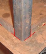
Strength is simply not an issue for the junction between the border pieces for the top of a bench. The important joint -- from that perspective -- is going to be the one that joins the legs to the top frame, along with what other type of support the legs might get (lower crossmembers, diagonals, etc.).

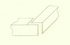
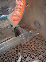
That said, the interlocking joint has one advantage over a miter joint. It's less likely to tear open like a zipper if you were prying the two pieces apart. A weld is theoretically as strong (or stronger) than the metal it joins. In practice, that's often not the case (we'd all like to be theory-level perfect welders, but we aren't). Interlocked seams might not fail in the same kind of zipper-like fashion (meaning: one straight-line seam that can be opened a millimeter at a time instead of having to fail all at once).

Then again, I'm not an engineer. So I could be way off base.

But as I said, the corner really gets no stress at all. I mean, you're attaching a top to this thing, right?
 
Last edited:

sberry

Banned
Joined
Jun 18, 2005
Messages
35,747
Location
Brethren, Michigan
Strength is irrelevent at this point, this type of joint doesnt have to be as strong as it can be, only adequate.
 

Attachments

  • bench connect 2a.JPG
    bench connect 2a.JPG
    45.1 KB · Views: 343
  • bench connect 2.JPG
    bench connect 2.JPG
    41.6 KB · Views: 303
  • bench connect 1aa.JPG
    bench connect 1aa.JPG
    35.7 KB · Views: 340
  • bench connect 1a.JPG
    bench connect 1a.JPG
    35.9 KB · Views: 338
  • bench connect 1.JPG
    bench connect 1.JPG
    33.5 KB · Views: 361
To avoid these ads, REGISTER NOW!
OP
K

Krokodil

Well-known member
Joined
Apr 11, 2010
Messages
1,428
Location
South Africa
Yes, I will just put the top onto this. Will I be able to accurately cut 45 corners freehand with a grinder?
 

sberry

Banned
Joined
Jun 18, 2005
Messages
35,747
Location
Brethren, Michigan
I built about 2 or 300 benches for a plant. Gang cut all the parts, used the same legs for any length bench and pre fabbed them in a jig, looked like an H with an angle added at the top. We would clamp the 2 long angles to the plate, stand up a set of legs, square it with the top and tack, stand the legs on other end up, tack, add steel for shelf in, this would square that set of legs and weld it all up, minimal short welds along angles to top plate, about 3 welds on a 5 footer and some weld at the corners like in the pics. Took maybe 20 or 30 mins. Each unit had maybe 3 ft of weld in about a dozen spots.
 
Last edited:

e-tek

Well-known member
Joined
Dec 19, 2007
Messages
10,690
Location
Saskatoon, SK
Not likely - that's why they (Jack, etc) are saying use the overlap!! (PS - I'd use the square-tubinbg approach shown in sbery's final pic)
 

sberry

Banned
Joined
Jun 18, 2005
Messages
35,747
Location
Brethren, Michigan
Yes, I will just put the top onto this. Will I be able to accurately cut 45 corners freehand with a grinder?

Precision just doesn't matter in some things. When I gang built the stuff I figure out how to do it all with straight cuts so pieces can be gang sawed. Its really a fairly rare day I have to miter something.
 

Jack Olsen

Super Moderator
Staff member
Joined
Mar 22, 2009
Messages
6,678
Location
Los Angeles
Krokodil, I think you're making this a lot more complicated than it needs to be. Look at sberry's pictures; you can make a strong bench without overlap or miter cuts.

What are you using for legs -- angle or square tubing?
 

Quiksilver

Well-known member
Joined
Jun 22, 2006
Messages
333
Location
Loveland, OH
Does the angle have to face inward? If there will be an overhang I don't see why you couldn't do something as simple as this. I stole sberry's idea and the red represent the welds.

outside%20weld%20corner.png


inside%20weld%20corner.png
 

Wanna Ride

Well-known member
Joined
Jul 28, 2010
Messages
2,790
Oh for the love of god... it's a ******** workbench. What are you going to put on it a railcar? Sheesh.
 

babzog

Well-known member
Joined
Apr 20, 2009
Messages
2,117
Location
Eastern Ontario, Canada
Oh for the love of god... it's a ******** workbench. What are you going to put on it a railcar? Sheesh.

Well, if it were me, I'd be using it as a learning experience. Use the workbench project to learn cutting, fitting, joint-making, welding, etc. Better to learn and make mistakes there than on something where proper assembly matters. I know that I know next to jack diddly squat about this stuff so this thread is interesting to me.
 

Wanna Ride

Well-known member
Joined
Jul 28, 2010
Messages
2,790
Agreed. But for the application being discussed, either method will more than suffice.
 

sberry

Banned
Joined
Jun 18, 2005
Messages
35,747
Location
Brethren, Michigan
A lot of effort isn't needed on the corners, any weight bears on the post. Most important is having just heavy enough piece as re-enforcement along the long span across the middle. I have seen huge fab benches and unless I really needed one I don't care for them, about 3x6 is plenty, some even smaller but i like to be able to reach across and be able to walk around easily. I also like the shelf up from the floor. Keeps a lot of dirt off of stuff stored there and makes it easy to sweep under.
My own benches are a cobbled mess, needed them when they were needed and were patched and added from scraps. They worked well enough they just haven't got upgrades. I went to auction the other day where there was one I had an eye on that would have made a great start over, 3/4 top and beam legs but when it went past 200 and looked to be no end in site I passed.
 

Attachments

  • bench3a.jpg
    bench3a.jpg
    36.6 KB · Views: 182
  • bench3.jpg
    bench3.jpg
    37.7 KB · Views: 204
  • bench2a.JPG
    bench2a.JPG
    63.8 KB · Views: 227
  • bench2.jpg
    bench2.jpg
    43 KB · Views: 235
  • bench1a.JPG
    bench1a.JPG
    43.2 KB · Views: 231
  • bench1.jpg
    bench1.jpg
    36 KB · Views: 241

sberry

Banned
Joined
Jun 18, 2005
Messages
35,747
Location
Brethren, Michigan
Kind of cobbled with lots of stuff added. Probably more since these were taken. The chop saw is long gone. It was a real mess, made its own containment.
 

Attachments

  • bench wrenches.JPG
    bench wrenches.JPG
    55.6 KB · Views: 171
  • bench wrenchess.JPG
    bench wrenchess.JPG
    42.3 KB · Views: 168
  • chop bench2.JPG
    chop bench2.JPG
    33.1 KB · Views: 241
  • chop saw deflector.JPG
    chop saw deflector.JPG
    77.5 KB · Views: 186
  • Chop bench mess.JPG
    Chop bench mess.JPG
    72.2 KB · Views: 198
Last edited:

Steve in Mi

Well-known member
Joined
Mar 13, 2007
Messages
1,042
Location
Mid Michigan
Last edited:

csp

Well-known member
Joined
Mar 23, 2010
Messages
5,719
Location
Franktown, CO
Are you sure about that?:)

Has nobody here ever used these shear, notcher and bender tools;

Read the last sentence in the post you quoted. "It's all in how your shop is setup."

The OP is asking about making accurate miters with an angle grinder, so it's pretty safe to assume that he doesn't have access to a notcher.:thumbup:
 

Steve in Mi

Well-known member
Joined
Mar 13, 2007
Messages
1,042
Location
Mid Michigan
OP asked for ideas, I provided an idea. Turns out my idea makes most of what you said (and I quoted) mistaken. Don't get your ******* in a knot but there was no mention of a welder or grinder in the original post, only cutting.

I don't make assumptions about what tools the guy has or may want to purchase.
 

gorilla

Well-known member
Joined
Dec 13, 2007
Messages
1,649
Steve in Mi, I am very familiar with the Roper Whitney equipment you mentioned IMHO it's junk! You can't hold better than a 1/4" with it on a good day and it"s a PIA to use. Sberry you have a shop that looks like a lot of work can be done quickly and well. I agree with you about chop saws my shop had a 10 hp chop saw with a 24" wheel it cut pretty good but what a mess. Nice to know that so many people are willing to help a fellow JG member.
 
OP
K

Krokodil

Well-known member
Joined
Apr 11, 2010
Messages
1,428
Location
South Africa
Thanks for all the participation guys! My intention was never to start a debate or to question anybody's (incl my own) fabrication skills. I merely wanted to know what fabrication technique you prefer for a specific type of joint with pros and cons of each. It is very interesting to get different opinions from different folks. I have learn a lot from your answers and will build my bench in the next few weeks. I ordered my 10mm mild steel top today.

Will post updates as soon as I come back from leave!

Happy wrenching.....
 

sporkedtospec

Well-known member
Joined
Jun 21, 2009
Messages
57
Location
Raleigh, NC
I just wrapped up a new fab table and used 3x3" 1/4" angle. The design turns the frame outward so the inside angle is facing outside. I mitered the joints using a 4.5" angle grinder. In fact, the entire table was cut to length using around 25 cutoff wheels. Including trimming both sides of the 3x4' surface, 1/4" leg radiuses, and all of the trim-to-lengths...around 60 feet of cutting with a 4.5" grinder and all of that with thickness no less than 1/4".
A reciprocating saw was not any faster and a grinder is all I have at my disposal.

I found the best way to cut a 45 into the angle was to layout with a combination square and follow the line as close as possible. I did not try to follow the 45 degree cut through the other side, meaning both cuts 45 and 90 where perpendicular to the face. All of the joints were trued up with a 14" coarse-cut flat file.

This method left a flat seam along the 45 degree joint that had to be ground a bit with a root pass and small cap for around 3/4 penetration. The 90 cut left a 90 degree toe that required a single root pass and a weave fill pass for complete penetration with a bit of drop through where the seam wasn't completely true.

Entire table was done with TIG.

Will post pictures shortly, may clear up any confusion from above.
 
To avoid these ads, REGISTER NOW!
Top Bottom