Radio Flyer
Well-known member
Can anyone help me ID this connector/terminal? The OE is of no help. Thanks in advance for the help!

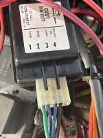


Yes! “Card edge connector” is the magic search term. Now to sift through 697,000 varieties.does that mate onto the Printed Circuit Board (PCB) is my guess by teh pin type. Search for PCB Card edge connector.
What does the front end of it look like?
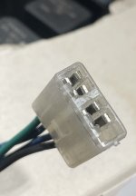
does that mate onto the Printed Circuit Board (PCB) is my guess by teh pin type. Search for PCB Card edge connector.

Closest in that pic seems to be this. It's not the same though.
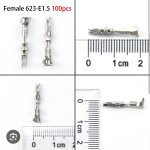
I spotted that one too, it’s a teaser.Closest in that pic seems to be this. It's not the same though.

I've been known to do that, adding a more readily available connector a few inches away.My first attempt was to build up with some solder, in hopes to create a better contact area. But it didn’t work. Now I’m thinking of soldering some wire directly to the board and doing away with the connector completely.
Where did you get that? On the old molex connectors at with, we would pull the crimp pins, scrub then with an eraser, spray some contact protector and reassemble. I would expect the connector to be more of an issue than the traces/contact on the boardThe connector and terminals were never the issue? The PCB was worn out? I missed that. Thought this was about replacing the terminals and connector.
Yes. I have done that many timesWhere did you get that? On the old molex connectors at with, we would pull the crimp pins, scrub then with an eraser, spray some contact protector and reassemble. I would expect the connector to be more of an issue than the traces/contact on the board
So this is the long version.The connector and terminals were never the issue? The PCB was worn out? I missed that. Thought this was about replacing the terminals and connector.
That board is pretty basic and it would not be all that hard to duplicate a new one, tin it and swap or duplicate components. Also there are places that sell replacement adhesive pads that can be glued on and soldered to. There are also businesses that do that repair that sort of thing if you need that assistance.
It was clear to me that you simply wanted to replace the connector from the get go. Your pictures, before and after depin, and request for information was spot on. You had clearly designed wire “B” on the connector.So this is the long version.
The board is a low coolant module. The low coolant light was on 100 per of the time with the ignition on. Troubleshooting determined that it was a module issue. A new module was installed and the light went out. However, the light would flicker at times when going over bumps and such. I was able to duplicate it by twisting and turning connector at the module. I de-pinned the connector and squeezed the terminals to tighten up the connection, with no real change. I then tried to add some thickness to the solder on the board. No change there either. So I wanted to just replace the connector. And here we are…..
So this is the long version.
The board is a low coolant module. The low coolant light was on 100 per of the time with the ignition on. Troubleshooting determined that it was a module issue. A new module was installed and the light went out. However, the light would flicker at times when going over bumps and such. I was able to duplicate it by twisting and turning connector at the module. I de-pinned the connector and squeezed the terminals to tighten up the connection, with no real change. I then tried to add some thickness to the solder on the board. No change there either. So I wanted to just replace the connector. And here we are…..
How's the housing fit to the enclosure?
This may not be a terminal issue, especially if you've bent them tight and added thickness to the board.
How about the actual sensor end ? In the coolant.It just sets in the bottom, and the top snaps into it. Reminds me of how a key fob gets assembled.
I had just thought with a new module, and new connector, I’d have a better chance at a good outcome.
The sensor is brass and uses 2 eyelets. One in the center (probe) and the other screwed into a flat of the hex (ground) it was replaced due to coolant leaking from the center. So it’s new by default.How about the actual sensor end ? In the coolant.
Try resoldering this joint. Never know…..The sensor is brass and uses 2 eyelets. One in the center (probe) and the other screwed into a flat of the hex (ground) it was replaced due to coolant leaking from the center. So it’s new by default.
The real issue is that I can replicate the flickering light by giggling the connector on the module (board).

I’ll check tomorrow, but I think it’s just a rivet type connection.Try resoldering this joint. Never know…..
Probably. Sometimes it’s a ground plane bond between top and bottom traces on the board. I haven’t seen topside.I’ll check tomorrow, but I think it’s just a rivet type connection.

 findpigtails.com
 connectorexperts.com
try this page infinite97 linkedAs a heavy equipment tech I run into this **** all of the time. Try these websites:
Shop Automotive Connectors
Discover a wide range of automotive connectors, pigtails, and plugs at findpigtails.com. Lightning-fast search, helpful tools, and how-to repair guides available. Trusted by dealerships and insurance.Automotive Connectors | Connector Experts
Looking for the best automotive connectors on the market? Connector Experts has an expansive collection of products. Shop for top-quality connectors.
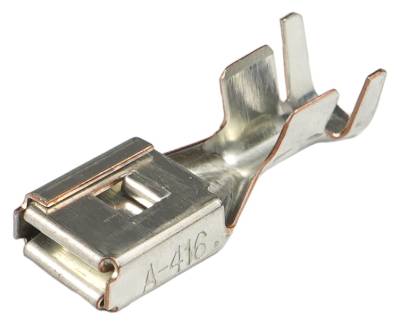
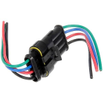
Thanks, I did find that site. This one is close, but may not work.

