Bobnoxious32
Well-known member
So I started planning my welding bench build some time in 2018.
I went through many of the forums here to steal some ideas!")
The main things it has to include:
Be compact (small workshop!)
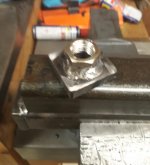
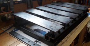
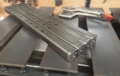
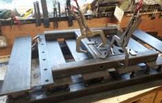
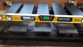
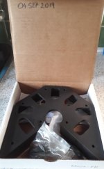
Slotted Top Plates (Im heavilly invested in C Clamps / G Clamps already)
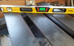
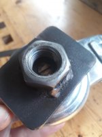
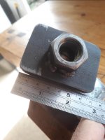
Top Plates have to be level adjustable
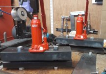
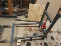
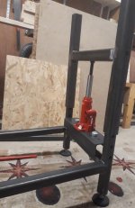
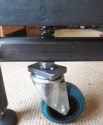
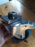
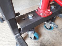
Be portable with hydraulic jack lowering castors.
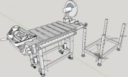
Be height adjustable (Inspired by the Fireball Tool Bench design)
Be height adjustable with the same castor hydraulic jacks (Cleverest feature).
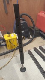
Have height adjustable levelling feet.
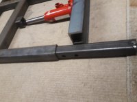
Have extension bars for long stock.
Accessories:
Tool Storage:
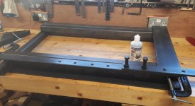
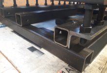
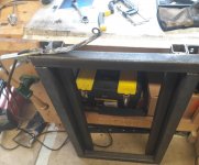
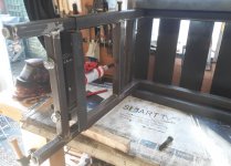
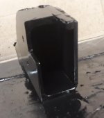
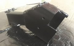
At this point i have a lot of the Bench built, but it is still work in progress.
More updates to follow!
I went through many of the forums here to steal some ideas!
The main things it has to include:
Be compact (small workshop!)
Slotted Top Plates (Im heavilly invested in C Clamps / G Clamps already)
Top Plates have to be level adjustable
Be portable with hydraulic jack lowering castors.
Be height adjustable (Inspired by the Fireball Tool Bench design)
Be height adjustable with the same castor hydraulic jacks (Cleverest feature).
Have height adjustable levelling feet.
Have extension bars for long stock.
Accessories:
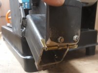
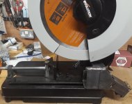
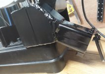
- Hold my Evolution Chop Saw level with the clamping plates.
- Spark catcher for the chop saw
- Hold my 2x72" belt grinder (Jeremy Schmidts design: if you havent bought Jeremys plans already you need to buy them and build that machine, finest addition to the workshop).
- The bench must allow the 2x72" belt grinder to rotate 90° so needs 1 short plate to allow the Motor pivot.
- Include Extension slots for a Vise.
Tool Storage:
- C Clamps, G Clamps,
- Angle Grinders
- Invertor Welder
At this point i have a lot of the Bench built, but it is still work in progress.
More updates to follow!


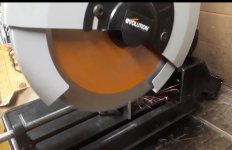
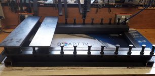
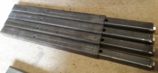
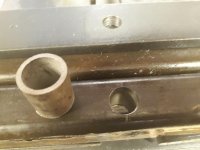
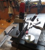
 !) Makes short work of the holes once you use some of that machining/cutting lube. The cutting fluid and swarf/chips makes a right mess, thats when i introduced the old TV cardboard box to protect the Roubo Woodworking bench i built a few years ago.