FliesLikeABrick
Member
Antique pump rebuild - advice needed
Hello everyone,
While on vacation last week, a new project followed me home - an old pump with electric motor, from back in the woods behind a lakeside camp where it was their on-hand firefighting pump 50 years ago.
I have the motor running (old Century Electric Co repulsion start/induction run motor, ca 1947 1hp), and am now turning my attention to the pump.
The pump is from the 20s-30s (this electric motor retrofitted to the frame later). The main seal on the shaft seems to be a felt/wool packing impregnated with grease.
Pictures for context:
.jpg")


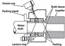
The part that I need input on and have not been able to make much progress on is a part that bolts to the frame at/around the pump's input.

The above picture is with the piece in question, a cast iron "flange" shaped piece, unbolted from the frame and tilted to the 2:00 position, that cup is normally pointing up vertically.
As you screw the top of the cup down, it pushes grease down into the journal around the shaft.
The end of this piece that faces towards the pump actually fits into the frame, compressing the packing inside; so it would make sense if this cup/grease mechanism was meant to inject grease into that area. However:
- It is on the far end of the cast component instead of closer to the seal
- This piece's ID has a step in it -- it is narrower towards the pump, and larger towards the motor. This means that any grease forced inwards will generally just ooze towards the motor.
Here are approximate measurements of the diameters in question:
- The shaft is 1.343"
- The narrower ID of the component in question is 1.382", this end faces the pump
- The larger ID of the component in question is 1.495", this end faces the motor and is the ID that has the grease cup/fitting on it
Here are some other pictures:

The cup with the cap off. In this picture it is not bolted in place, but this the location and orientation that it sits in

This is where it sits, with the camera facing towards the back of the pump. The bolts are still removed, the piece in question is slid back from the pump. Where the shaft enters the frame, you can see the darker grease-impregnated wool/felt bushing/seal

Above, the piece on the table - screwing the cap down pushes grease into the opening
So my questions:
- Can anyone provide some input on what this setup is meant to accomplish?
- Is something perhaps missing, like another wool/felt packing inside of this piece that would keep the grease from oozing towards the motor? I don't think so, since the OD is wider on that end and such packing would just be pushed out by the grease.
Of course any other input on this pump would be welcome.
Hello everyone,
While on vacation last week, a new project followed me home - an old pump with electric motor, from back in the woods behind a lakeside camp where it was their on-hand firefighting pump 50 years ago.
I have the motor running (old Century Electric Co repulsion start/induction run motor, ca 1947 1hp), and am now turning my attention to the pump.
The pump is from the 20s-30s (this electric motor retrofitted to the frame later). The main seal on the shaft seems to be a felt/wool packing impregnated with grease.
Pictures for context:
The part that I need input on and have not been able to make much progress on is a part that bolts to the frame at/around the pump's input.
The above picture is with the piece in question, a cast iron "flange" shaped piece, unbolted from the frame and tilted to the 2:00 position, that cup is normally pointing up vertically.
As you screw the top of the cup down, it pushes grease down into the journal around the shaft.
The end of this piece that faces towards the pump actually fits into the frame, compressing the packing inside; so it would make sense if this cup/grease mechanism was meant to inject grease into that area. However:
- It is on the far end of the cast component instead of closer to the seal
- This piece's ID has a step in it -- it is narrower towards the pump, and larger towards the motor. This means that any grease forced inwards will generally just ooze towards the motor.
Here are approximate measurements of the diameters in question:
- The shaft is 1.343"
- The narrower ID of the component in question is 1.382", this end faces the pump
- The larger ID of the component in question is 1.495", this end faces the motor and is the ID that has the grease cup/fitting on it
Here are some other pictures:
The cup with the cap off. In this picture it is not bolted in place, but this the location and orientation that it sits in
This is where it sits, with the camera facing towards the back of the pump. The bolts are still removed, the piece in question is slid back from the pump. Where the shaft enters the frame, you can see the darker grease-impregnated wool/felt bushing/seal
Above, the piece on the table - screwing the cap down pushes grease into the opening
So my questions:
- Can anyone provide some input on what this setup is meant to accomplish?
- Is something perhaps missing, like another wool/felt packing inside of this piece that would keep the grease from oozing towards the motor? I don't think so, since the OD is wider on that end and such packing would just be pushed out by the grease.
Of course any other input on this pump would be welcome.
Last edited: