To avoid these ads, REGISTER NOW!

Any framing pro's in the house?

Smitty75

Active member
Joined
Dec 10, 2015
Messages
26
Trying to layout the front wall of my garage build. Measures 32' across, and each pier or stem wall between the 3 doorways is 14" tall x 18.5" wide. 2 garage doors are each 11' wide and the man door is standard 36". 9/12 bonus trusses will run perpendicular to the front wall. Block foundation with 80% of the blocks filled with concrete (every 3').

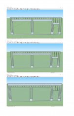
Attached is the framing sketch ideas so far. Original plan was the top diagram, inspector suggested (not required) the middle diagram, and a framing buddy suggested something similar to the last sketch. Walls are 2x6 framing, and headers are 2 11-7/8" lvl's (I've got 2 36' Lvls available). Any suggestions from the group? I have been reading a lot about continuous span beams and the potential for wall buckling due to a lack of lateral support, so being that this is well beyond 18' I'm assuming sketch 2 is not the best option, but not sure about the bottom sketch and if running against the top plate helps the issue. Sorry if it's a dumb questions, this is my framing 101 course.
 

Attachments

  • Garage Front.jpg
    Garage Front.jpg
    53.6 KB · Views: 461
To avoid these ads, REGISTER NOW!

Stuart in MN

Well-known member
Joined
Sep 8, 2005
Messages
23,088
Location
Minneapolis
I think the bottom sketch will allow you to make changes in the future - assuming the LVL is sized to support that whole side of the garage, you could switch to a double wide garage door later, or otherwise change the framing underneath the LVL if desired. On the other hand, putting up one big LVL will be more difficult than several smaller ones.

Where are you located? There may be local requirements to take into account potential seismic activity.
 

Jlbc212

Well-known member
Joined
Dec 7, 2013
Messages
1,530
Location
Northeast MA
My garage is similar in size - 36 ft long and 28 feet deep with two 12 foot wide doors and a 3 foot wide door all on the long, roof supporting wall side. I used the method shown in your first picture. The walls are just over 12 feet high. I built it 5 years ago and it hasn't collapsed yet.

I keep wondering how the old barns, garages and houses in New England haven't collapsed or blown away without the "benefit" of shear walls and foundation anchors. Most of the foundations on structures built before the 50's are stone. Many of those have no mortar between the stones. Yet, they are still there.
 

jkeyser14

Well-known member
Joined
Dec 19, 2008
Messages
1,819
Location
(rural) Maryland
#3 is the weakest design as the bottom 2x4 will have a huge tensile load on it instead of the LVL taking the brunt of the load. You should either go with #1 or #2. #2 would be fastest to frame but is probably a bit more expensive.
 

readhead

Well-known member
Joined
Dec 8, 2012
Messages
6,177
Location
Durango, Co.
Several questions come to mind. First, where are you? This is a pretty critical wall and I would think that specific details would have been on the plans directing the shear and nailing patterns. The first plan will be easier to build in three sections and stand up if you don’t have any equipment. For that size header you are definitely looking at double trimmers for the garage door openings. I would go back to whoever did the plans and have them clarify the details.
 

ddurrett896

Well-known member
Joined
Mar 29, 2015
Messages
995
Location
VA
#3 is the weakest design as the bottom 2x4 will have a huge tensile load on it instead of the LVL taking the brunt of the load. You should either go with #1 or #2. #2 would be fastest to frame but is probably a bit more expensive.

What bottom 2x4s are you referring to?
 

kasander

Well-known member
Joined
Jun 7, 2016
Messages
424
Location
Wilmington, NC
I am assuming that this is on the gable end wall of the garage. If it is on the eave side, you need more jack and king studs, and you need it engineered to meet code. My garage is very similar, but with the doors on the eave side. My engineer required 3 jacks and 3 kings for each side of each door. (I used design 1) I also have a 1 bedroom apartment upstairs which increases the load on the walls. For reference, mine is 26' deep, 30' wide.

Front wall is 2x6 framed, btw.

upper_walls_sheathed.JPG
 

Falcon67

Well-known member
Joined
Jun 11, 2009
Messages
18,371
Location
Merkel, TX
#1 easier to frame with available store bought lumber and likely a bit cheaper IMHO. #2 OK, just will likely require a big LVL ($$$) to go the distance.
 

firebirdparts

Well-known member
Joined
Jun 8, 2016
Messages
10,602
Location
Kingsport, TN
Ouch. With the trusses sitting on the wall in question, there's not much holding the house up. Not a trivial exercise in framing.

The roof itself will give you a ton of lateral support once it's all finished. And you sure don't have much else.
 

ddawg16

Well-known member
Joined
Jul 11, 2008
Messages
21,005
Location
S. California
If it were me.....I'd go #2 but do it all the way across like #3

Main reason....it will be easier to attach the garage door hardware. More surface area with wood.

In fact, I'd consider going taller on the beam so you don't have to use the studs between it and the top plate. Get an 5.5" wide LVL and you will have less issues matching things up. The added cost will be made up for with less labor. Or, go with a slightly taller door.

I would also put a Simpson Strong Wall in the middle and over at the right side for shear.
 

WNYflyer

Well-known member
Joined
Sep 13, 2009
Messages
2,119
Location
Lockport, NY
Being the gable end of the garage you will need to know how the possible "hinge" at the top of the gable wall and gable structure/truss is going to be eliminated. Studs running continuously up to the roof deck? Hinge joint braced back to the roof deck somehow? OSB, Plywood, etc. attached to the bottom of a couple of trusses to form a beam/diaphragm spanning from bearing wall to bearing wall to stabilize the joint? The framing sketches indicted really need to take into account the whole picture of how the structure is supposed to work so they can be worked out correctly.

Also, as already noted you need enough "meat" in the wall to act as a shear wall also or perhaps some proprietary shear panel products. Maybe take the man-door around the corner to get more shear wall?

A lot of things to think about to see the complete picture and get it right.
 

readhead

Well-known member
Joined
Dec 8, 2012
Messages
6,177
Location
Durango, Co.
It's not the gable wall. The trusses are bearing on this wall. This is usually when I would get a call to do a steel portal frame in one of the openings to provide the required shear value.
 
OP
S

Smitty75

Active member
Joined
Dec 10, 2015
Messages
26
As an update, this will be the eve side wall, not gable. All framing is 2x6 except the 11 7/8 lvl’s I already have access to so cost isn’t a factor. We are in upstate SC, so no particular snow or wind loads required. And I ran everything by the inspector, and he didn’t seem to care which way I went. As far as the architect route, in these parts all they do is floor plans and exterior elevations, then turn it over to the framers to figure out to frame it. I called several which were no help. i am also running this by a structural guy I know, but everyone around here does commercial, and won’t even call you back on residential unless it’s a big project. I waited 12 months just for concrete (which turned out to be a sloppy half *** job), so on my own except for a few favors from friends in the industry. There is a down side to a booming construction market lol, no one available. I appreciate all the feedback and will update once I hear back from my structural guy.
 

WNYflyer

Well-known member
Joined
Sep 13, 2009
Messages
2,119
Location
Lockport, NY
It's not the gable wall. The trusses are bearing on this wall. This is usually when I would get a call to do a steel portal frame in one of the openings to provide the required shear value.

Whoops, my mistake.
In that case the first sketch is the only one that comes close to making sense since it has at least some studs at the OH door openings spanning from foundation to the top plate/bottom of trusses. Who knows if they are enough?
Possible hinge effect is on side walls then.
 
To avoid these ads, REGISTER NOW!

paredown

Well-known member
Joined
Jan 12, 2012
Messages
544
Location
Pomona, NY
I am assuming that this is on the gable end wall of the garage. If it is on the eave side, you need more jack and king studs, and you need it engineered to meet code. My garage is very similar, but with the doors on the eave side. My engineer required 3 jacks and 3 kings for each side of each door. (I used design 1) I also have a 1 bedroom apartment upstairs which increases the load on the walls. For reference, mine is 26' deep, 30' wide.

Front wall is 2x6 framed, btw.
Not and expert, nor do I play one on TV...but

This looks better to me--you want some meat on those corners, especially for those unforeseen events, like someone hitting them or hooking them with a bumper while pulling out... So sketch 1 with extras would be my vote. Isolating the LVLs also means you could (if you had to) get in there and replace one without disturbing the other.

The way that yours is done kasander, you have effectively posted the corners and center. Agree with the other post--that's a good job on that garage.
 
Last edited:

napaul

Active member
Joined
Oct 3, 2019
Messages
40
Location
edmonton,alberta
I just did something similar to repurpose the lvl's I used to lift my garage. ram 2 ply 14" lvl all the way across. I don't think you need to be concerned with lateral load as previously stated your roof will do most of that.
 

MoonRise

Well-known member
Joined
Nov 5, 2010
Messages
4,028
Location
NJ
Not a trivial question or solution.

Certainly do-able, just not as simple as stick up some studs and slap some OSB on it.

Best way to get the answer is an architect or a licensed Professional Engineer.

Very surprised that your locale didn't require the detailed plans (from either of those mentioned professionals), with their professional License stamp ON THE DRAWINGS.

Yes, you DO have wind loads that have to be dealt with. Depending on where in South Carolina you are located with respect to the coast, wind design loads can vary from 110 to 150 mph.

You need to consider or address the following items (not necessarily a comprehensive list):

- foundation hold-downs from stem walls to foundation

- anchor bolts from sill plates to stem walls

- hold-downs from walls to sill plates

- wind uplift

- wall shear

- wall stud/post compressive loads one the garage door wall (reduced number of studs carrying the roof loads because of the door openings)

- required structural wall sheathing panel thickness required

- shear wall load path from corner-to-corner

- tie straps from header to studs/posts

- tie straps from roof system to wall system

- required nailing patterns from shear wall to header and shear wall to studs (hint: it will probably be a MUCH denser nailing pattern than 'normal', as in a 3" OC nailing pattern from sheathing to the header and from the sheathing to the studs)

- top plate to header nailing pattern requirement is double rows of 16d at 3" OC typical

- minimum wall sections for your 'skinny' sections are 16" for an 8 ft high wall to the top plate to 20" wide for a 10 ft high wall to the top plate

You can check some of the tech details for narrow wall bracing and framing at the APA website at www.apawood.org.
 

kasander

Well-known member
Joined
Jun 7, 2016
Messages
424
Location
Wilmington, NC
Also, for my garage, sheathing is required on exterior and interior of the front wall to increase shear resistance. I have a steel beam running across the center, so the span from the center to the front of my garage is only 13'. Still quite a bit of load on a wall with two 9' wide garage doors and a man door. With 11' doors, you may need more than two 2x12 LVLs. Mine has 2 2x12 LVLs and I filled the gap between them with insulation so that they are 5.5" wide to sit on the studs. You may need 2x14 LVLS (do they even make those?) and 4 jack posts per side of each door. Either way, hire an engineer to do the calculations.

My build thread (in serious need of an update):

https://www.garagejournal.com/forum/showthread.php?t=354039

My engineering plans:

http://www.pelicanpointroad.com/garage/garage_eng_plans.pdf
 

2level

Well-known member
Joined
Apr 10, 2008
Messages
1,146
Location
Washington
My shop has a similar front wall layout but with larger overhead doors and no 36" door. Framers elected to use method #1 per your sketches.

Engineer spec'd out 5 1/8" x 18" Douglas fir Glulams, instead of LVLs, anchored to 4x6 posts. 36"x54"x16" reinforced poured concrete pad at center of overhead doors, and 36"x36"x16" pads at sides of doors. 8"x18" reinforced stem walls, and majority of footer is 15"x6".

They used 1/2" plywood sheathing and a 3" O.C. nail pattern, sheathing the inside of the narrow wall too. Galvanized steel tie straps embedded in stem walls and nailed thru sheathing into studs, and of course the walls/bottom plates were anchored to the stem walls/foundation . Also used tie straps between floors and from roof system to wall system. Engineered for 105mph wind uplift and low snow load.
 
Last edited:

DPG

Well-known member
Joined
Feb 9, 2014
Messages
473
Location
Western Colorado
All 3 options will work, but this is a question for your structural engineer since he will have to stamp the drawings that you have to submit for a permit.
 
OP
S

Smitty75

Active member
Joined
Dec 10, 2015
Messages
26
All 3 options will work, but this is a question for your structural engineer since he will have to stamp the drawings that you have to submit for a permit.

Unfortunately in this area, it’s rare or extremely difficult to find a residential structural engineer, and the county doesn’t require any plans or drawings for a permit. You tell a farmer what you want, and he starts building. I have reached out to a structural engineer I work with in industrial applications, just waiting on his assessment. But when I built my house 2 years ago, I paid big bucks to have an architect “design” my house, and literally all I received was a floor plan, rendition, and exterior elevation. Handed those mostly useless drawings to a foundation guy and a framing guy, and they got me a dried in house. Framer and lumber yard sized everything. Only issue now is that all the framers won’t even return a call unless it’s a $500k house. It’s backwards here so just trying to do what I can to get a good build.
 

paredown

Well-known member
Joined
Jan 12, 2012
Messages
544
Location
Pomona, NY
My shop has a similar front wall layout but with larger overhead doors and no 36" door. Framers elected to use method #1 per your sketches.

Engineer spec'd out 5 1/8" x 18" Douglas fir Glulams, instead of LVLs, anchored to 4x6 posts. 36"x54"x16" reinforced poured concrete pad at center of overhead doors, and 36"x36"x16" pads at sides of doors. 8"x18" reinforced stem walls, and majority of footer is 15"x6".

They used 1/2" plywood sheathing and a 3" O.C. nail pattern, sheathing the inside of the narrow wall too. Galvanized steel tie straps embedded in stem walls and nailed thru sheathing into studs, and of course the walls/bottom plates were anchored to the stem walls/foundation . Also used tie straps between floors and from roof system to wall system. Engineered for 120mph wind uplift and low snow load.

Are you Washington State--and meeting earthquake standards as well?

I remember our house in Seattle was pretty tied down because of that--and we went through that earthquake in '2001, and despite being a bit of a cliffhanger design, we had absolutely no damage...
 
OP
S

Smitty75

Active member
Joined
Dec 10, 2015
Messages
26
This is how I have it drawn up now, but will bring the lvls a bit wider and add in some additional bracing as previously suggested and see what the engineer has to say about potential shear issues. I don’t mind putting in a couple Simpson strong walls, but I think they are limited to a 6 or 8” tall stem wall and mine is 14” (I could be reading it wrong though). But the county already inspected the foundation, sill plates, and anchors, and said have at it as is. But I certainly want to do it right.
 

Attachments

  • 38D0EC33-F31F-4269-A84A-6A7EE2EA9ACA.jpg
    38D0EC33-F31F-4269-A84A-6A7EE2EA9ACA.jpg
    157.6 KB · Views: 66

DPG

Well-known member
Joined
Feb 9, 2014
Messages
473
Location
Western Colorado
Unfortunately in this area, it’s rare or extremely difficult to find a residential structural engineer, and the county doesn’t require any plans or drawings for a permit. You tell a farmer what you want, and he starts building. I have reached out to a structural engineer I work with in industrial applications, just waiting on his assessment. But when I built my house 2 years ago, I paid big bucks to have an architect “design” my house, and literally all I received was a floor plan, rendition, and exterior elevation. Handed those mostly useless drawings to a foundation guy and a framing guy, and they got me a dried in house. Framer and lumber yard sized everything. Only issue now is that all the framers won’t even return a call unless it’s a $500k house. It’s backwards here so just trying to do what I can to get a good build.

Wow. I had heard that places like that still existed. I thought it was a myth!
 

redneckcharlie

Well-known member
Joined
Dec 26, 2009
Messages
125
Here that would require an engineers stamp. Not really necessary. The lvl in that set up here to pass would have to run from side to side completely. The vertical supports would have to be strapped at the lvl locations at the top and at the bottom. At the top the strapping would have to be attached from the top plate across the lvl and down to ur studs. The bottom strapping would of had to be imbedded in the foundation and brought up and tied to across ur bottom plate and to the lower section of the studs. The strapping would have to be on top of ur sheathing material. Here either osb or plywood suffice for the framing inspection. When ur purchasing that much lvl the extra to go all the way across as a single member is negligible, regardless if they require it in ur local area or not. It simplifies the framing and will actually save you time in the end and make it vastly more structurally sound. Use the strapping wether they require it or not. It will greatly help in a high wind load and an uplift scenario. Its cheap insurance. You can tie the bottom strapping in to the outside of your foundation if need be as well. Its not as sound as being imbedded, but its much better then none at all. Anybody that would frame that with separate headers is being lazy and cheap, plain and simple. The difference between the cheap/lazy and correct way is 2-300$ max. That section of framing is not the place to skimp on ur build.
 
Last edited:

2level

Well-known member
Joined
Apr 10, 2008
Messages
1,146
Location
Washington
Are you Washington State--and meeting earthquake standards as well?

I remember our house in Seattle was pretty tied down because of that--and we went through that earthquake in '2001, and despite being a bit of a cliffhanger design, we had absolutely no damage...

Yes, south of Seattle. I just took a look at the engineering docs -- says Seismic Zone D1. Built in 2008/9, so may be different requirements now.
 
Last edited:
OP
S

Smitty75

Active member
Joined
Dec 10, 2015
Messages
26
Here that would require an engineers stamp. Not really necessary. The lvl in that set up here to pass would have to run from side to side completely. The vertical supports would have to be strapped at the lvl locations at the top and at the bottom. At the top the strapping would have to be attached from the top plate across the lvl and down to ur studs. The bottom strapping would of had to be imbedded in the foundation and brought up and tied to across ur bottom plate and to the lower section of the studs. The strapping would have to be on top of ur sheathing material. Here either osb or plywood suffice for the framing inspection. When ur purchasing that much lvl the extra to go all the way across as a single member is negligible, regardless if they require it in ur local area or not. It simplifies the framing and will actually save you time in the end and make it vastly more structurally sound. Use the strapping wether they require it or not. It will greatly help in a high wind load and an uplift scenario. Its cheap insurance. You can tie the bottom strapping in to the outside of your foundation if need be as well. Its not as sound as being imbedded, but its much better then none at all. Anybody that would frame that with separate headers is being lazy and cheap, plain and simple. The difference between the cheap/lazy and correct way is 2-300$ max. That section of framing is not the place to skimp on ur build.

Thanks, this is great information. A few comments, the purpose of the simple spans was more for lateral support as it seems like APA and a lot of articles online recommend simple spans with portals to achieve bracing requirements for narrow walls and still get lateral support to prevent buckling. I'm not so much worried about the cost of a continuous span if I can still get the required bracing and lateral support achieved using this method. I am still waiting on the engineer to get back to me though as I am obviously not a professional. One other thing I can do is go from 11' wide garage doors to 10' and get 24" of extra bracing to be distributed across 3 of 4 of the stem wall sections (currently 18.25" wide which would bring them to 24" wide), or use the extra 24" where best distributed. I'd like to make the 11' doors work, but can get by with 10' if need be.
 

mcbane

Well-known member
Joined
Jul 23, 2017
Messages
794
Location
California
"Unfortunately in this area, it’s rare or extremely difficult to find a residential structural engineer".

At least in CA, "Structural" engineer is an additional credential that a civil engineer obtains. It permits design of high rises and unconventional structures. Civil engineers are limited to 5 stories tall.

So if you are demanding a structural engineer rather than a civil engineer, you are trying to hire someone who likely is specializing in commercial projects and is unlikely to be interested in a simple residential design.
 

scottydosnntkno

Well-known member
Joined
Aug 8, 2010
Messages
670
Architects have been mentioned twice: They are not qualified to design this. That is not what they do.

Depends on the state but many do, and are licensed to. I know our architect we use for our houses has a masters or architecture and holds a current michigan architecture license and all our plans come with his aia stamp on them, with all the beams, LVLs, etc specd out. He doesn’t use an outside engineer

All three options would work assuming they all meet NC code. The code book usually has diagrams and specifications for all the wall types.

In michigan, we ‘portal frame’ all our wide or double opening garage walls. The LVLs span from corner to corner right above the OHDs , so it’s a combination of 2 and 3. Then everything is shear nailed 3” o.c and 6’ simpson straps are used inside and outside vertically to hold it all together
 
To avoid these ads, REGISTER NOW!
Top Bottom