A 1/2" is nothing, it's normal. My trusses are only a few weeks old and I can go out and push them up or pull them down that much. 24" span. They are designed to have some deflection in them. Wood is never straight especially with spans that long. Go look at some new dimensional lumber, you won't find a straight piece in 12 foot like used in trusses.


You are using an out of date browser. It may not display this or other websites correctly.
You should upgrade or use an alternative browser.
You should upgrade or use an alternative browser.
Any truss experts here? Sagging question.
- Thread starter 1233user
- Start date
Trey T
Well-known member
Exactly! When I redid my joist for attic space, I needed five 2x10x21ft grade 1 SYP but I ordered 10 of them and select the best one to use and I'M GLAD I DID.A 1/2" is nothing, it's normal. My trusses are only a few weeks old and I can go out and push them up or pull them down that much. 24" span. They are designed to have some deflection in them. Wood is never straight especially with spans that long. Go look at some new dimensional lumber, you won't find a straight piece in 12 foot like used in trusses.
I really appreciate all the replies, you guys are great! I have an appointment with a structural engineer tomorrow afternoon to have him look at the pictures, the truss drawing, and ask him about the discrepancies in the load data on the truss sheet. I took more pictures today to show him, and I am more concerned now with all the spaces where the truss plates are. Down at the bottom where the rafter part of the truss meets the ceiling joist part there is a space on at least half the trusses. The space on most of those is between 1/8" and 1/4", but there are a couple that are 3/8". With a lot of snow on the roof there has to be tremendous downward pressure in that area, which has to be all taken by those truss plates since there is no wood to wood contact.


There is also a space between the rafter and the 2x4 that makes the "raised heel"


There is also a space between the rafter and the 2x4 that makes the "raised heel"

theoldwizard1
Well-known member
Measure the distance across the floor and then at the top plate, The difference should be zero, but less than 1" is probably acceptable.
Start putting a level on things. I would bet that the outside walls have shifted and are not plumb,
No, unfortunately I didn't measure or check anything at first. I really wish I had now so I had something to reference against. Although I only strung out a few of them, every one that I strung out was sagging. Also, by eyeing down the trusses from the side, they all show some sag.
The purpose of the bottom chord is to 1) prevent the walls from bowing out and 2) to pick up some of the load from the rafters via the web.
Measure the distance across the garage at the bottom plate and the top plate.
David C
Well-known member
In review of your latest photos; can you describe the blocking construction that occurs between roof trusses? It appears there is plywood screwed to something.
There should be solid wood blocking between trusses. The horizontal plywood roof diaphragm must have a direct connection to the exterior plywood shear walls. Normally this force is transferred by nailing the roof ply to the block, and the shear wall ply to the same block.
You might draw a cross section detail cut through the block and show it to your SE.
Why the caulk? Blocking between trusses should be tight to each truss. There should be no gaps.
And the insulated attic space must be vented. Air leakage at these joints would only increase the attic ventilation. It would not be necessary to seal these air tight.
The carpenter really slammed the gun nails into those H clips. This is not a good practice.
Last edited:
The purpose of the bottom chord is to 1) prevent the walls from bowing out and 2) to pick up some of the load from the rafters via the web.
Measure the distance across the garage at the bottom plate and the top plate.
I just went out and measured this in a few places, the worst spot was 1/4" larger at the top than it is at the bottom. That was almost in the middle of the garage. It was probably like that from the day it was built though, because in the middle we had a small space between the wall plywood and the end of the trusses but the trusses were almost touching the wall plywood on both the ends. The wall plywood goes up about 5" higher than the top of the walls, this made things easier when we were installing the trusses because the overhanging plywood located them side to side.
In review of your latest photos; can you describe the blocking construction that occurs between roof trusses? It appears there is plywood screwed to something.
There should be solid wood blocking between trusses. The horizontal plywood roof diaphragm must have a direct connection to the exterior plywood shear walls. Normally this force is transferred by nailing the roof ply to the block, and the shear wall ply to the same block.
You might draw a cross section detail cut through the block and show it to your SE.
Why the caulk? Blocking between trusses should be tight to each truss. There should be no gaps.
And the insulated attic space must be vented. Air leakage at these joints would only increase the attic ventilation. It would not be necessary to seal these air tight.
The carpenter really slammed the gun nails into those H clips. This is not a good practice.
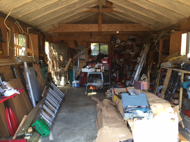
The plywood that you are seeing in the pictures that has caulking on the side is actually my home made soffit baffles. The trusses overhang the walls on the outside by about a foot or so, and there is a 2x6 that runs across and attaches to the ends of all the trusses. I made my own baffles because I didn't like any of the premade baffles I could find. I am going to do blown in insulation, and I wanted to make sure that it didn't have any way to get out of the attic. I made nailers to space the plywood 1 3/4" off the bottom of the roof decking so there is plenty of room for air flow. Here are some pictures to explain it better:
This is what it looked like before I put the soffit baffles in. You can see the 2x6 that is nailed to the ends of the trusses.

Here is a picture of what my home made soffit baffle looks like.

And here is a picture of it installed showing the nailers and the space for air movement below the roof decking.

David C
Well-known member
The most recent pictures show what I was afraid of. Your building is missing a critical connection between the horizontal plywood diaphragm and the shear walls. I don't know what the standard of care is in Connecticut but in the Western states this would be considered non code compliant and unapprovable. I would not sign any document that accepted this building and I would write you, your contractor, and the building department a letter stating that.
With that said CT is a long ways away, you do not have earthquakes, and I don't know what is typically accepted there. I have seen some very unusual construction in the midwest and east.
You should show this to your SE and tell him that some wise guy (or wise ***) on the internet said that you don't have a horizontal ply diaphragm connection to you shear walls. See what he says.
So, I met with the structural engineer today. He didn't seem overly concerned with the spaces, he said that some of it is due to shrinkage of the wood, and some of it due to sloppy manufacturing by the truss company. He didn't like the fact that the BCLL was 0 in the specifications part of the spec sheet, and only called out in detail in the notes below. He said that it looked to him that I got what I wanted, but he wanted to run calculations on everything just to be sure because of the discrepancy in the load numbers. I am going to go back early next week and see what he came up with, but right now as far as he is concerned I really don't have a problem. He said that the sag I am seeing probably happened over the last 2 winters when there was a lot of snow on the roof. He said that trusses don't really spring back as much, they kind of move where they are going to and then stay there.
Any thoughts on his initial opinion?
Any thoughts on his initial opinion?
The most recent pictures show what I was afraid of. Your building is missing a critical connection between the horizontal plywood diaphragm and the shear walls. I don't know what the standard of care is in Connecticut but in the Western states this would be considered non code compliant and unapprovable. I would not sign any document that accepted this building and I would write you, your contractor, and the building department a letter stating that.
With that said CT is a long ways away, you do not have earthquakes, and I don't know what is typically accepted there. I have seen some very unusual construction in the midwest and east.
You should show this to your SE and tell him that some wise guy (or wise ***) on the internet said that you don't have a horizontal ply diaphragm connection to you shear walls. See what he says.
Thanks David, I really appreciate all of your replies! I am trying to picture exactly what it is your talking about that I am missing? Are you saying that there should be a blocking piece that goes between the trusses, sitting on the top sill of the wall and running all the way up to the roof sheathing? If so, I don't think I have ever seen that done around here. Do you have a picture or drawing of what you're describing?
The most recent pictures show what I was afraid of. Your building is missing a critical connection between the horizontal plywood diaphragm and the shear walls. I don't know what the standard of care is in Connecticut but in the Western states this would be considered non code compliant and unapprovable. I would not sign any document that accepted this building and I would write you, your contractor, and the building department a letter stating that.
With that said CT is a long ways away, you do not have earthquakes, and I don't know what is typically accepted there. I have seen some very unusual construction in the midwest and east.
You should show this to your SE and tell him that some wise guy (or wise ***) on the internet said that you don't have a horizontal ply diaphragm connection to you shear walls. See what he says.
you live in earthquake country. blocking in between trusses is usually not done in most other parts of the country. truss ties are used though, for heavy winds.
Homerr
Well-known member
Thanks David, I really appreciate all of your replies! I am trying to picture exactly what it is your talking about that I am missing? Are you saying that there should be a blocking piece that goes between the trusses, sitting on the top sill of the wall and running all the way up to the roof sheathing? If so, I don't think I have ever seen that done around here. Do you have a picture or drawing of what you're describing?
David is talking about something like what is labeled "2X VENTED BLOCKING PER ARCH" in this detail. It keeps the trusses from falling over like dominoes against each other.

Denwood
Well-known member
There would no code issues with those trusses here either. As far as the gaps, I'd be willing to bet best practice would have the gaps at zero (as you've suggested) so load is transferred to the wood, not the truss plates. The truss plates are not designed to take compression so much as shear. If the truss plates can handle compressive load beyond the web max loading, then it would a non-issue. It's a good question to raise with your engineer.
http://www.ashireporter.org/homeinspection/articles/inspecting-wood-trusses/1213
This article makes a good point with respect to movement of trusses due to moisture content and season. There is an expectation that the bottom chord will rise/fall slightly with moisture changes in the wood.
http://www.ashireporter.org/homeinspection/articles/inspecting-wood-trusses/1213
This article makes a good point with respect to movement of trusses due to moisture content and season. There is an expectation that the bottom chord will rise/fall slightly with moisture changes in the wood.
theoldwizard1
Well-known member
Then "structurally" they are doing their job.I just went out and measured this in a few places, the worst spot was 1/4" larger at the top than it is at the bottom. That was almost in the middle of the garage.
I hope they are toe nailed to the top plate. Those hurricane ties stop the truss from lifting up, but don't do much in the way of stopping the wall from moving out or in.
Last edited:
David C
Well-known member
I have added red pencil marks to the section detail provided by Homer to illustrate what is missing and why. This detail was likely created by an architect because there is redundancy in the connection of the blk to the shear wall ply, and the nail images are omitted. I also added a detail from my own garage which I have just finished building for reference.
For your building, or any wood framed building, to resist lateral forces (wind or seismic) there must be a series of connections to transmit the lateral forces to ground. Think of these connections as a chain.
When the wind blows on a bldg the aerodynamic forces are transmitted from the plywood roof diaphragm to the BN, to the solid blk, to the EN in the shear wall ply, down the shear ply to (not shown) an EN to the sill plate and from the sill plate to the concrete sill plate anchor bolt, to the footing and ground. Hard to read, go slow and follow with a pencil on the section details. Every element of this chain of connections is required.
Any bldg missing a single link in this chain will not preform well under wind (or seismic) loads.
Contrary to what has been said here the solid block and diaphragm boundary nail, omitted from your bldg. is almost certainly required in all areas of the US and Canada as well. This is how wood structural design is taught in every US university and how the codes are written regardless of geographical location.
The reason that earthquakes and the western US get mentioned here is that because of EQ's the western region of the US understands the need for well designed, and constructed, bldgs, even those as small as residences. As a result the industry, (architects, engineers, plan reviewers) emphasizes these connections. The same connections would be required to resist wind loads in Connecticut and Maine.
What I have observed (on a very very limited basis) is that the midwest and eastern portions of the country do not seem to emphasize structural engineering design for small bldgs in the same manner as the west. Residential construction in these areas of the country get the least attention. Likely because there are few failures.
Florida, and other locations subject to hurricanes have become more concerned with structural design particularly after, I think it was Andrew, and have modified their codes and emphasized structural engineering for all bldgs including residences. The east coast it seems, not so much.
While others on this board have noted that these blocks and nailings are regularly omitted in their area this would not be because it isn't required, it simply isn't considered important or enforced. This is not true for residential and other small buildings in the south and west.
You have a very long building with two narrow walls at the gable ends. Resisting wind loads might be important to you. I don't know what the standard of care is in Connecticut which is why I suggested you discuss this with your SE.
Attachments
Denwood
Well-known member
David, the truss blocking detail you indicated is definitely not part of the building code here in Ontario. Currently (at least for now) you don't require hurricane straps in Thunder Bay either. There is a toe nail spec..and that's it. With raised heel trusses, many builders will carry exterior sheathing right up to the top chord, however that's more for insulation retention. If you're anywhere pre-disposed to seismic activity, (as you are) I'd expect added requirements in the top plate area.
Trey T
Well-known member
If what David proposed is true, then there's no intake for ventilation. If there is blocking between the trusses, it must not extend to the roof sheathing, because that prevent any air flow from coming in. In california where the temperature and weather is consistent throughout the year, you can probably get at least 20-yr out of 30-yr shingle w/o ventilating the roof; however, in Texas, you be lucky to get 20yrs out of 30yr shingle even if it's properly ventilated.
I don't need to get into structural analysis but that ventilation part alone doesn't make sense to me.
I don't need to get into structural analysis but that ventilation part alone doesn't make sense to me.
Last edited:
David C
Well-known member
Just to keep things going.
Denwood, I would bet you can't show me in the Canadian code where it says blocking is not required. Probably you couldn't find where it says it is required either.
To explain: Canadian and US buildings are required to withstand proscripted loads. These include wind loads.
In Canada, and the US, buildlings must have a structural system that adequately resists these proscribed loads. In a wood framed building with fabricated trusses, plywood diaphragm and shear walls, there must be a method to transfer horizontal shear to vertical shear walls. Additionally the horizontal diaphragm has to have boundary chord elements. These requirements are achieved, almost universally, with blocking and nailing as noted previously. The diaphragm chords are the continuous top plates. The explanation of diaphragms and chords is way beyond the scope of any posting on this site. But the physics is the same in Canada as the US.
Canada almost certainly has the same requirements, the loadings might be different, but the construction methods are not. Additionally later forces can be resisted in other ways but what I have shown is how it is typically done in wood frame construction. And while it is possible to devise another method it would cost considerably more. For these reasons I would be a lot of money that the blocking and nailing as shown is required in Canada. Not with a provision that says you must block and nail, but the through the provision where it says you must resist lateral wind forces.
One other comment on this; that you may have constructed a building in Canada, or seen other buildings constructed in Canada (or Connecticut, Maine, Ohio etc), without this blocking, or that contractors have told you it is not required by code, or even that your building department did not require it, does not mean it isn't required by Canadian codes. It is way too much to go into here regarding building departments and what they are actually asked to do, what they are capable of accomplishing, and are liable for (nothing).
The building codes in the US are state law. Hence the term code. These are adopted by the state legislatures into state law. Violation of a code provision is against state laws. Not sure what it is in Canada but it is likely similar. You might think of the building department as an overworked and underfunded police station. They have interest in enforcing only the code provisions (laws) they feel up to, or are required to by politics.
As to the attic ventilation; this is universally required by most codes. However there are many ways that code specified attic ventilation can be provided, other than through the eaves. Gable end vents are one way, ridge vents, and eyebrow vents are others. In my area of CA attic ventilation is critical because of the rain and humidity which would, and has, caused dry rot damage to the underside of plywood roof covering in unvented attics.
I also live in the country and there are new WUI (wildlife urban interface) regulations that among other requirements precludes eave venting. This is because of the way forest fire flames go into a building through eave vent openings. If you look at my eave section, the one for my own garage, you will see that my eave is protected and that there is no eave venting. I used gable end vents.
Trey T
Well-known member
David, not every building will have two gable ends, some just have one. Gable intakes are not proper to cool the roof deck, they can circulate the air but not proper like intake from eaves. The other vents you mentioned are not commonly use as intake, just exhaust.
what you saying is the ideal structural design but that's not sacrificing for proper ventilation. There's no such thing as ideal design, engineering, or construction. In Cali, the annual precipitation is nothin compare to other states and temp variation is not significant. In areas of Cali, I can see improper ventilation is acceptable but not around here.
I think you have doubt on strength of OSB material; believe me they are crazy strong and resilient. Therefore, sheathing the wall up to bottom of top chord will create a proper shear wall
Last edited:
gdh33
Well-known member
To sum it up, I think there is proper design and construction. But most areas, states, provinces build differently for reasons specific to the region. I for one was told and just ran my OSB up to the bottom of the top chords. Nailed the OSB well to the wall, top plates and rafter ends. I have also not witnessed or heard of any garages or houses falling over or caving in. How we construct houses and garages today is much more thought out and engineered. I feel fine, building inspector says its fine. To each their own. Appreciate the input and discussion though.
Denwood
Well-known member
David, you're correct in that I can't show you code requirements for the truss blocking you describe, because they're not there. My most recent project was our own 10 000 sq/ft net zero project here at Cinevate for which I was the GC. Like all commercial projects here, we required an architect, and stamped drawings for mechanical, structural, electrical, and ESA certification for electrical. This project required two separate in-place truss modifications, (clerestory addition, and vaulting from 8 to 11 ft over a 900sq/ft area). Permits and inspections here are rigorous. Insisting that solid blocking at the truss plate interface is required by law etc etc is pointless in that professionals here tend to build to code to avoid legal issues. It's important to consider that folks here on the journal are posting from all over the world. Grossly off topic, but these are from the drawings on our truss mods at Cinevate.

While our seismic activity is zero, with zero risk of hurricane, and no recorded instances of tornadoes, we do have a 40psf snow load requirement...and code here reflects those requirements.
Gd, glad to hear you've had your questions answered") . Your baffling setup is pretty typical of what you'd see here, however most would do it with corrugated styro baffles at the roof deck. If you had elected to spray foam the underside of your roof deck, code here would allow zero ventilation providing the prescribed thickness of closed cell was used. When converting my shop ceiling from stick framed to ridge beam, that's exactly what we did. In that case the eaves are sealed completely off.
. Your baffling setup is pretty typical of what you'd see here, however most would do it with corrugated styro baffles at the roof deck. If you had elected to spray foam the underside of your roof deck, code here would allow zero ventilation providing the prescribed thickness of closed cell was used. When converting my shop ceiling from stick framed to ridge beam, that's exactly what we did. In that case the eaves are sealed completely off.
The beam structure etc is visible here:

While our seismic activity is zero, with zero risk of hurricane, and no recorded instances of tornadoes, we do have a 40psf snow load requirement...and code here reflects those requirements.
Gd, glad to hear you've had your questions answered
. Your baffling setup is pretty typical of what you'd see here, however most would do it with corrugated styro baffles at the roof deck. If you had elected to spray foam the underside of your roof deck, code here would allow zero ventilation providing the prescribed thickness of closed cell was used. When converting my shop ceiling from stick framed to ridge beam, that's exactly what we did. In that case the eaves are sealed completely off.The beam structure etc is visible here:
Last edited:
Homerr
Well-known member
Here in Seattle our engineer has given us a detail that shows permissible cut out areas for ventilation in the blocking in a separate detail than what was posted. We always show blocking here, as do truss shop drawings. This is for residential construction.
Trey T
Well-known member
Correct. I didn't want to get into the code a such.... but:
"placing a block b/t trusses for lateral forces" are considered a procedure or standard of practice in that region; that's not a code.
A code would specify something like "determine proper shear value for specific lateral forces (i.e. wind or seismic)"
"placing a block b/t trusses for lateral forces" are considered a procedure or standard of practice in that region; that's not a code.
A code would specify something like "determine proper shear value for specific lateral forces (i.e. wind or seismic)"
David, you're correct in that I can't show you code requirements for the truss blocking you describe, because they're not there. ...
...
I just wanted to post a final update on my truss concerns. I met with the structural engineer again yesterday. He did his calculations on the trusses, and said that all his numbers came in at or better than the specs on the sheet so it looks like everything is ok. I questioned the spaces again, and he said not to worry about them, they were mostly due to shrinkage of the wood. The larger spaces he thought were a combination of shrinkage, and careless assembly by the truss company. I also asked him about the blocking that has been talked about here, and he was familiar with it, but said it wasn't something that was usually done in this part of the country. So it looks like I can continue on with my project. Thank you everyone for all the input and advice! You guys and this site are great!!!
DangerousDan55
Well-known member
Just thinking, how.about adding some plywood gusset plates glued & fastened over the top of the metal gusset plates. Thats what I did at my duaghters garage when I installed an attic stairway. Her house is 40 years old and her wood joints under the metal gusset plates was stil.a good fit. I decited to add the ply wood plates due to the joists are 2x4s. The majority storage will be over the wall framing.
ssdave
Banned
The trusses are fine. The connections with gaps are okay, also, as long as the trusses are laterally braced. The truss members should be in tension instead of compression, and the plated truss fasteners are good for that loading.
The trusses might actually straighten out a bit with more loading. Loading the trusses will tend to spread the trusses out slightly, putting tension on the bottom cord, and tending to straighten it out. Loading the bottom chord with sheetrock ceiling, will put the interior members in tension, transferring it to the top truss member, and causing it to spread out.
I would just finish the work and not worry about it.
Trey T
Well-known member
You a structural guy? That was something I was gonna say but I don't practice in that area to make any suggestion w/o actual calculation.
The trusses are fine. The connections with gaps are okay, also, as long as the trusses are laterally braced. The truss members should be in tension instead of compression, and the plated truss fasteners are good for that loading.
The trusses might actually straighten out a bit with more loading. Loading the trusses will tend to spread the trusses out slightly, putting tension on the bottom cord, and tending to straighten it out. Loading the bottom chord with sheetrock ceiling, will put the interior members in tension, transferring it to the top truss member, and causing it to spread out.
I would just finish the work and not worry about it.
ssdave
Banned
You a structural guy? That was something I was gonna say but I don't practice in that area to make any suggestion w/o actual calculation.
General Civil, a lot of experience in building. I don't think I could come up with a calculation that would give a definitive answer to the bottom chord bowing question. Too many generalizations and idealizations in truss calculations, in reality they don't act exactly as the ideal truss models predict because the plated truss connections don't act as ideal connectors, and the mass of the beams themselves is significant.
By the trusses are fine, I don't mean I checked the load ratings. I'd rely on the truss manufacturers to have done that correctly, as they have double checked and verified to the OP. What I mean is the gaps and the bottom chord deflection don't indicate a problem.
Last edited:
HemiMan
Member
Not true - check the under the "FORCES" tabulation in the truss calcs and you will see several members with compressive forces, some over 3000 pounds (yes, I am a licensed Structural Engineer).The trusses are fine. The connections with gaps are okay, also, as long as the trusses are laterally braced. The truss members should be in tension instead of compression, and the plated truss fasteners are good for that loading.
The trusses might actually straighten out a bit with more loading. Loading the trusses will tend to spread the trusses out slightly, putting tension on the bottom cord, and tending to straighten it out. Loading the bottom chord with sheetrock ceiling, will put the interior members in tension, transferring it to the top truss member, and causing it to spread out.
I would just finish the work and not worry about it.
ssdave
Banned
Not true - check the under the "FORCES" tabulation in the truss calcs and you will see several members with compressive forces, some over 3000 pounds (yes, I am a licensed Structural Engineer).
Hemi-man, you're absolutely right, and I stand corrected. I didn't see the truss diagram and force tablulation the first time, not sure why I only saw the pictures.
The members that have the high compressive forces are the top chords. The verticals where the picture of the gapped connection was taken show a 7 pound compressive maximum if I'm reading the load tabulation correctly. The bottom chord does show a moderate compressive load (not sure under what loading conditions) but a substantial tensile load, again, not sure under what loading condition. I have a good guess as to what balanced/unbalanced conditions would produce those loads, but I won't speculate again!
I should have taken a closer look at the truss and diagram and/or done calculations before I gave a general answer.
However, looking at the load tabulation, and the truss configuration, I still don't see that there is any cause for concern from the deflection observed, nor the shrinkage or fabrication gaps shown.
David C
Well-known member
Hemiman, I note that you are an SE in the east. Might you take a moment to explain some of the issues raised in the posts above. I don't know why I want to know, outside of just general curiosity, but here goes;
Most, if not all, building codes in the US, (maybe even Canada too) originate from the IBC. California, and probably many other states, amend this code and adopt it (the IBC with amendments) for state wide application. As a result most US building codes are remarkably similar and include wind design requirements.
Buildings are required to withstand (and Earthquake) lateral loads. While the eastern US probably does not have EQ requirements they almost certainly have wind load requirements.
What I noted from the OP's photos was that his garage was missing the connection from the horizontal plywood diaphragm to the shear walls. This would normally be done through nailing the roof ply to the full depth solid block and the shear wall ply to the same block.
Lacking this block, and related nails and clips, there is no connection of the horizontal ply diaphragm to the wall top plates and as a result there are no horizontal diaphragm chords.
The trusses are also not fully braced at the top chord. I note the plywood roof but the entire assembly could parallelogram.
Lacking the above noted elements and connections the building would not comply with the wind load requirements of the IBC (and the versions adopted by most states) and would result in poor performance of the building under lateral wind loads.
QUESTIONS:
Is it normal practice in the eastern US to ignore this (wind load) portion of the code?
Or is it that there simply little attention given to wind loads on small residential buildings?
Is structural engineering taught this way in the east? It isn't in the west.
The OP's SE said he is familiar with the idea of solid blocking but it isn't done in CT. This is such a divergence from what is done here that I can't really imagine it. Is there some explanation that I might be completely missing?
buening
Well-known member
In our area (Seismic Zone 2, but does get to 4 near St Louis, MO), small scale buildings such as a garage do not get the same high level critique as would a public building that requires an SE seal and building plan review. One can build a house around here without any design or PE/SE seal required. Ultimately the Contractors know what the building inspector likes, and it gets built to those minimum requirements.
Blocking is not done in any of the buildings that I've seen around here with trusses. Sheathing ends at the top plate, with the eave cavity between trusses open and will typically have the styrofoam eave vents stapled to the roof sheathing (provides opening between roof and insulation where top chord ends). FWIW, they just recently started requiring the seismic straps to be installed, so seismic implementation is a slow moving process.
Blocking is not done in any of the buildings that I've seen around here with trusses. Sheathing ends at the top plate, with the eave cavity between trusses open and will typically have the styrofoam eave vents stapled to the roof sheathing (provides opening between roof and insulation where top chord ends). FWIW, they just recently started requiring the seismic straps to be installed, so seismic implementation is a slow moving process.
David C
Well-known member
Buening, Thanks for the response and information.
In general what you say is true in IL is true here though I think our smaller, less important, structures, get more attention than IL. Here it depends upon the location with the more urban areas requiring better design. In the rural areas not so much. I think most of the contractors have come to expect, and will install, the blocking. They do not understand diaphragm chords or the connections between horizontal ply diaphragm and shear walls so if left to their own devices it is hard to say what is constructed.
Regardless the code still requires a structural design that transfers wind loads to ground. The blocking and related connections are required simply not installed in all buildings.
In CA a civil engineer can do structural design with some exclusions. The structural designation requires a CE license, additional experience, and a two day test. Is this the same in IL?
If an IL SE were to design a medium size wood structure would he include connections between the horizontal ply diap and shear walls? Would he check diaphragm chord forces? Would he know what a collector is?
D
buening
Well-known member
Yes in Illinois we are required to pass the 16hr SE exam, and anything structural in nature must be sealed by a licensed SE. Civil Engineers with only a PE are not allowed to touch anything structural here in Illinois. California and Washington used to require an additional seismic exam on top of the NCEES 16hr exam, but that is no longer required.
Yes the seismic analysis and detailing is likely very similar to that in California. Wood structures are not overly common in public structures here, so seismic detailing is often misunderstood based on my experience. Concrete, steel, and masonry are more common and detailing better understood.
Yes the seismic analysis and detailing is likely very similar to that in California. Wood structures are not overly common in public structures here, so seismic detailing is often misunderstood based on my experience. Concrete, steel, and masonry are more common and detailing better understood.
David C
Well-known member
Buening,
Thanks for the answers. It does explain alot.
I have designed a number of wood framed schools and wood is commonly used here for low rise construction. Schools and hospitals are plan reviewed by SE's and they will not approve drawings, with poor detailing, for construction. In cases where there is no detailing of the connection between horizontal diaphragm to shear walls, or diaphragm chords, or no bracing of trusses at supports, they would simply send the drawings back for correction.
buening
Well-known member
Interesting to see wood framed schools. All schools around here (again, relatively low seismic Zone 2) are typically split faced CMU