To avoid these ads, REGISTER NOW!

Anyone able to help with this controller (wiring)

The Cobbler

Super Moderator
Staff member
Joined
Oct 24, 2013
Messages
26,087
Location
Niagara Region, Ontario, Canada
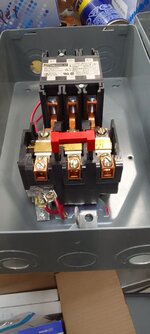
This controller was given to me by someone that said it should work for controlling my 5 HP frankenstein compressor I am eventually going to put together.
I don;t know much at all about magnetic controllers. Anyone that can guide me with this is much appreciated . I do think I have to change a thermal break to properly protect the motor . I guess I need to know where to connect the load, the motor and the pressure regulator ( if this can be used that way .
Thanks , ask any questions needed.
1732241052193.jpeg

1732241094552.jpeg
 
To avoid these ads, REGISTER NOW!

TurnipTruck

Well-known member
Joined
Aug 28, 2005
Messages
1,595
Location
Southcentral Alaska
Does the cover have a diagram?

I can’t tell what voltage the coil needs, you probably can take the front plastic cover off and it will be stamped/molded/tagged somehow.
The 3 brass things near the bottom with “B45” , those are called heaters and you need to look up what amperage they pop at. When any of the heaters pop, the clear plastic switch underneath with red wires opens the circuit to the coil and the main power drops out. If they are rated too high or any value too low you will need different heaters. The red bar resets the heaters after they cool off.
Single phase 240v will use only two of the three contacts. Power enters at 1L1, 3L2,and/or 5L3.
The white plastic thing underneath with red wires may be the coil. Your pressure switch circuit will likely be wired in series to neutral and the unused tab.
The motor leads connect to T1,T2,and/or T3.

Not a professional.
Arc faults can spray molten copper at your face at the speed of an explosion.

Want a picture of my similar starter?
 
OP
T

The Cobbler

Super Moderator
Staff member
Joined
Oct 24, 2013
Messages
26,087
Location
Niagara Region, Ontario, Canada
I can't get any more pics right now, but the coil is 240volt
if I break one ( or both) of the red wires with a switch, does that open the contact? and then if the switch get closed, does the contactor re engage?
 

mm08822

Well-known member
Joined
Jan 13, 2012
Messages
6,141
Location
NJ
I can't get any more pics right now, but the coil is 240volt
if I break one ( or both) of the red wires with a switch, does that open the contact? and then if the switch get closed, does the contactor re engage?
No, those reds put the overload relay contacts in series with the coil. If ol relay trips there won't be continuity between 1L1 and the coil.

You need to also put a pressure switch connected from "3L2" back to the other side of the coil terminal.
Either buy a pressure switch with an on-off lever or add an on/off selector switch.

That is the control circuit described above.

Next you have incoming power to the starter connecting to 1L1 and 3L2.
Your motor connects to T1 and T3.
You will need a jumper from T2 up to 5L3.

You will also need to buy 3 overload heaters based on the motor FLAs. There should be a chart helping you to determine what size heaters needed.

Needs to be a hardwired connection to power.
Is panel in site of motor and less than 50'?

.
 
Last edited:

TurnipTruck

Well-known member
Joined
Aug 28, 2005
Messages
1,595
Location
Southcentral Alaska
The control circuit starts at 1L1 , then existing red wire to the T1 heater clear plastic block contact, then other existing red wire back to the white coil block.
Downstream side of the coil is the unused spade connection. That will eventually end up at neutral for a 120v coil or 3L2 for an 240v coil after going through the pressure switch contacts.

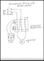
Found this diagram on here someplace and don’t know who made it.IMG_0276.jpeg

This particular contactor needed the power to go through all three contacts to be happy, otherwise the motor T leads would just go to T1 and T2 without going through T3.
 
Last edited:
OP
T

The Cobbler

Super Moderator
Staff member
Joined
Oct 24, 2013
Messages
26,087
Location
Niagara Region, Ontario, Canada
thanks, I think I get it . I guess my only questions ( right now) does T2 have to jump to L3 or can T2 go directly to the motor , and use L3 & T3 to run a 120volt hour meter?
and the wire to the pressure switch need to be #10 , or do I fuse it or?
 

TurnipTruck

Well-known member
Joined
Aug 28, 2005
Messages
1,595
Location
Southcentral Alaska
The last time I amp checked a coil it was one amp, so fusing it for 5 can’t hurt. I usually see #14 control wires even in 4160 cabinets.
If the contactor doesn’t need load balancing, you absolutely can use two contacts for the motor and the third for anything else. Might want a different heater or even a blank heater, depending upon the load.
Don’t forget an “enabled” lamp to remind you that the compressor is going to wake you up in the middle of the night.
 

mm08822

Well-known member
Joined
Jan 13, 2012
Messages
6,141
Location
NJ
The overloads won't function properly (generate proper amount of heat) if only 2 of the 3 are used. This can cause the motor damage if overloaded and starter not trip soon enough.

This is where the cover with the heater charts come in to play for various ambient conditions, etc

IIR, #14 will be ok for the external control wiring without fusing. There are some conditions to meet/not exceed, but code book not handy.
 
Last edited:
To avoid these ads, REGISTER NOW!

Norcal

Well-known member
Joined
Mar 16, 2008
Messages
13,774
but if they can be jumped with a brass bypass,how is that different than a pc of wire?
There is a little bar that mates with the pawl on the heater, it has to be held back or the overload relay will not reset, that is one of the quirks of SQ D.
 

mm08822

Well-known member
Joined
Jan 13, 2012
Messages
6,141
Location
NJ
There is a little bar that mates with the pawl on the heater, it has to be held back or the overload relay will not reset, that is one of the quirks of SQ D.
So then 2 heaters of an incorrect (larger size) could do same. Just need to have 1 heater sized properly and in one of the 2 poles completing the ckt to the motor.

If that is the case, then OP only has to buy one item - a single heater element.
 
OP
T

The Cobbler

Super Moderator
Staff member
Joined
Oct 24, 2013
Messages
26,087
Location
Niagara Region, Ontario, Canada
buy one item - a single heater element.
that's what I am hoping.
I've got a long ways to go till I get to the electrical. so far all I have is a bunch of parts. a motor, tank, compressor, etc etc. all new parts that I have acquired along the way. what started it was a 4 cyl.Dewalt ( Jenny) compressor for $ 25 that was missing the LH bolt to attach the flywheel .
 

Norcal

Well-known member
Joined
Mar 16, 2008
Messages
13,774
So then 2 heaters of an incorrect (larger size) could do same. Just need to have 1 heater sized properly and in one of the 2 poles completing the ckt to the motor.

If that is the case, then OP only has to buy one item - a single heater element.
NOPE! the jumper kit is needed to do the job properly when using a 3Ø overload relay in a single phase application, still cheaper then using 2 heaters & leaving one of the existing heaters in the center pole.
 

Norcal

Well-known member
Joined
Mar 16, 2008
Messages
13,774
NOPE! the jumper kit is needed to do the job properly when using a 3Ø overload relay in a single phase application, still cheaper then using 2 heaters & leaving one of the existing heaters in the center pole.
If you doubt me, remove 2 heaters & try to reset the O/L relay.
 

mm08822

Well-known member
Joined
Jan 13, 2012
Messages
6,141
Location
NJ
NOPE! the jumper kit is needed to do the job properly when using a 3Ø overload relay in a single phase application, still cheaper then using 2 heaters & leaving one of the existing heaters in the center pole.
What I meant was 2 existing heaters of a larger (wrong size) will be in-place instead of the plates you linked to. They would physically keep the o/l contacts from opening as the ratchet is restrained.

Additionally, a 3rd heater (properly sized) and installed in 1 of the 2 poles completing the motor circuit provides the protection.

1732333469208.png
 

mm08822

Well-known member
Joined
Jan 13, 2012
Messages
6,141
Location
NJ
Cobbler, here is you your heater chart...........note the fine print and column headers.

1732333601989.png
The way the heater selection is shown in the table, your options appear to be:
  • use 1 heater and and 2 jumper plates. Heater selected using single phase column
or
  • use 3 heaters properly sized and motor current needs to run through all 3 heaters (jumper wire from motor side term back to line side term)

The difference between the single phase and three phase motor currents for the same heater size relates back the the overall heating effect the overload relay housing experiences.
 
Last edited:
To avoid these ads, REGISTER NOW!
Top Bottom