To avoid these ads, REGISTER NOW!

Atlas Model 53 Speed reducer bearing removal

2humble

New member
Joined
Apr 25, 2024
Messages
4
Hello All - This is my first post, so bear with me.... My "new" Atlas model 53, overall is in good shape AND has the speed reducer which I am thrilled about. I am not doing a restoration, just a clean-up and use.

I have never used a speed reducer but the bearings in this definitely need to be replaced. Can anyone give me some pointers on how to remove the bearing without damaging the aluminum pulley?

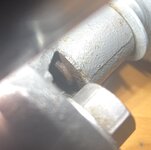
It seems that a way to do this, is to drive the shaft (marked A in photo) out of the bearing but, this might put too much stress on the bottom of the pulley. Is there a way to create a puller of some sort or some alternate method?

If these secondary questions should be a seperate thread, please let me know..... Should reducer be allowed to swivel as needed or should it be fixed securely by the bolt (marked B in the photo)? I'm guessing that when the belt positions are changed it is loosened and then re-tightened when tension is correct. Lastly, has anyone found a chart showing belt positions and speeds for this model with speed reducer?

Many thanks!
 

Attachments

  • IMG_1687.jpg
    IMG_1687.jpg
    1,003.3 KB · Views: 33
  • IMG_1676.jpg
    IMG_1676.jpg
    423.4 KB · Views: 30
  • IMG_1678.jpg
    IMG_1678.jpg
    525.7 KB · Views: 29
  • IMG_1677.jpg
    IMG_1677.jpg
    701.7 KB · Views: 28
  • IMG_1680.jpg
    IMG_1680.jpg
    265.6 KB · Views: 32
To avoid these ads, REGISTER NOW!

Provincial

Well-known member
Joined
Sep 21, 2011
Messages
6,882
Location
Near Salem, OR
Do you have access to an exploded parts diagram for the speed reducer? That will tell a lot about how it is made.

Don't apply much force to anything if you are not absolutely sure what will happen. Often, things are put together with no expectation that they will be serviced later.

After doing some research, you appear to have a model W14B speed reducer. You might contact Clausing, as they have a reputation for being helpful, to the point of supplying blueprints of parts they no longer supply.
 
Last edited:
OP
2

2humble

New member
Joined
Apr 25, 2024
Messages
4
Hi Provincial and thanks for your response. I haven't been able to find a diagram yet after much looking. There are many variations that Atlas / Craftsman made variously called Multi-speed Attachment and Slow-speed Attachement. There is a seller on ebay offering a 3d-printed one that seem to be similar and it appears to be a press fit for the pulley and the bearing. On your advice I will just oil it and use it as is for now instead of breaking the assembly, turns out they are going for $200-300 for the reducer alone and I got the press for $75. If anyone else comes across this thread with any more info, this particular reducer is marked W14 A1
 

crguy

Well-known member
Joined
Jan 24, 2016
Messages
2,676
Location
SW Washington
I would recommend a split collar that would fit in the bottom of the small pulley groove to support the pulley while you press the shaft out in an arbor press. Those pulleys are fragile.
 

shibertus

Well-known member
Joined
Nov 13, 2018
Messages
279
This is a different model Atlas speed reducer but looks like yours may go together similarly. If you can remove the shaft/pulley assembly from the bracket, then the shaft and bearing could be tapped out from there.

Screenshot 2024-05-17 at 10.13.44.png
 
OP
2

2humble

New member
Joined
Apr 25, 2024
Messages
4
Shibertus thanks so much for the diagram. It looks like spindle may indeed be threaded into the cast base. Based on this diagram I cant use a split collar to remove it because the shaft has a lip. I dont have any welding equipment to hold the bearing from moving, so the only other thing I can think of to remove the spindle is to drill and tap a 3/8"-1/2" hole in the top (fourth picture from the left) and use a bolt. Any other ideas?
 
To avoid these ads, REGISTER NOW!

shibertus

Well-known member
Joined
Nov 13, 2018
Messages
279
Shibertus thanks so much for the diagram. It looks like spindle may indeed be threaded into the cast base. Based on this diagram I cant use a split collar to remove it because the shaft has a lip. I dont have any welding equipment to hold the bearing from moving, so the only other thing I can think of to remove the spindle is to drill and tap a 3/8"-1/2" hole in the top (fourth picture from the left) and use a bolt. Any other ideas?
I would guess there has to be an easier way to get the shaft and pulley assembly separated from the base. My guess is they should come out as one unit, then the shaft and bearing can be tapped out of the pulley. Can you post some more photos of how it attaches to the base? Maybe that pin can be unthreaded to allow the shaft to come out?

If you want to try removing the bearing from the top, you could remove the grease shield which may allow you to grab the inner race with the jaws of a puller.
 

Provincial

Well-known member
Joined
Sep 21, 2011
Messages
6,882
Location
Near Salem, OR
alfadan is right. The pulley may have corroded and bonded to the bearing outer race. Heating to 200 degrees in an oven for an hour should expand the pulley bore enough to break any grip.

If I had to take this apart, I would first remove the pulley/spindle unit from the casting, and remove the bearing plate. Then make a support from a piece of pipe or round stock that fits the flat surface where the bearing plate bolts to the pulley., with the inside diameter slightly bigger than the bearing outer race, and the outside diameter big enough to support the whole flat surface. This would support the pulley in the best possible way. I would then heat the assembly for 2 hours at 200 degrees and use a press to apply a few hundred pounds of pressure on the threaded end of the spindle, keeping the nut on the treads to protect them. The bearing should press out easily, so stop if it puts up much resistance and regroup. I would use an arbor press in order to "feel" the pressure, since hydraulic presses give almost no feedback.

Edit to include removing the bearing plate in the instructions.
 
Last edited:
OP
2

2humble

New member
Joined
Apr 25, 2024
Messages
4
It’s very hard to get a good photo of the bottom of the spindle but you can see from the side there are no threads visible so most likely a press fit. Thanks Alfadan, i will use some atf/acetone penetrant and heat, for a few cycles. I prefer the strategy of taking the spindle out first, so whoever inherits this later will have an easier time. The geometry does not allow the spindle to be pushed out of the base, so I’ll ask a friend to use a split bearing puller (thanks crguy). If that doesn’t take it off very easily, I’ll remove the bearing cover and pull the races out from the top. When reassembling do you recommend using anti-sieze on the spindle?

Life is interfering with this project for a bit, but i will report back when i make some progress.
 

Attachments

  • IMG_1737.jpeg
    IMG_1737.jpeg
    700.7 KB · Views: 10
  • IMG_1736.jpeg
    IMG_1736.jpeg
    1.1 MB · Views: 10
To avoid these ads, REGISTER NOW!
Top Bottom