To avoid these ads, REGISTER NOW!

Atlas No54 Benchtop Drill Press Motor Wiring

H0w13

Member
Joined
Jul 16, 2021
Messages
21
Location
NJ
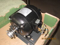
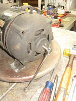
I just acquired a 1940's Atlas benchtop press from FB Marketplace and I'm a bit confused about the motor wiring.

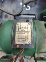
The motor is a K-C Bearing motor (from North Plainfield NJ!) that can do both 110 and 220v.

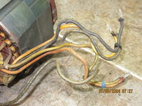
According to the wiring diagram, I *believe* the motor is currently wired for 220 but it has a 110 plug on it. Would using it in this configuration have damaged the motor at all? I plan on using it on a 110 circuit.

1728480057559.png

1728480071325.png

1728480083154.png
 
To avoid these ads, REGISTER NOW!
OP
H

H0w13

Member
Joined
Jul 16, 2021
Messages
21
Location
NJ
It's possible that the previous owner ran 220v on a 110 outlet, there was a lot of questionable choices in the shop when I went to pick up the press (bandsaw mounted to the stairs, for example).

Since I'm using 110 I suppose there's no real damage to be done if I wire it up both ways. The real trick is going to be determining the red vs yellow wires after 80 years of fading.
 

micromind

Well-known member
Joined
Sep 24, 2023
Messages
3,099
Location
Fernley, Nevada, about 30 miles east of Reno.
It's possible that the previous owner ran 220v on a 110 outlet, there was a lot of questionable choices in the shop when I went to pick up the press (bandsaw mounted to the stairs, for example).

Since I'm using 110 I suppose there's no real damage to be done if I wire it up both ways. The real trick is going to be determining the red vs yellow wires after 80 years of fading.

The black one hanging out the bottom of the box will have continuity to red. The green one will have continuity to yellow.

If 1 and 2 get swapped, no big deal....it'll run backward. Swap them and it'll run in the other direction.
 

Beerhippie

Well-known member
Joined
Oct 13, 2023
Messages
10,002
Location
Far NE Oregon
If you feel up to removing the back cover, I've found that the wires are usually less bleached out and easier to see the original colors inside the case.

BTW, if you try to run it wired for 220 on 110, it'll be pulling twice the Amps. Since it's only rated at 3 A for 220, that would be 6A at 110. Probably not enough to pop a breaker or burn anything up, but I'd expect it to get pretty warm--and significantly reduce the life of the windings.

This is why I always get pissed when I catch an employee running my 15A Skilsaw (or other high-draw tool--but the Skilsaw is mine) off a 50', 16 AWG extension cord. Long, small wires=voltage drop=higher amperage and more heat in the windings and cord.
 
Last edited:
OP
H

H0w13

Member
Joined
Jul 16, 2021
Messages
21
Location
NJ
I wired everything for 110 and nothing exploded! Those HF knockoff Wago connectors turned out to be great for this, though I'm not sure if I'd trust them sealed up in a junction box in my walls just yet.

There's definitely a noticeable power increase. Unfortunately, the motor is pulling 7.5 amps, with occasional spikes up to 7.8. Way higher than it's rated for.

I'm crossing my fingers that the higher draw is due to the grease drying out over time and general gunk that has built up causing the motor to have to work harder to spin, but I'm not holding my breath. Guess it's time to crack this thing open.
 
OP
H

H0w13

Member
Joined
Jul 16, 2021
Messages
21
Location
NJ
If you feel up to removing the back cover

Any advice on this? I've gotten the front (top?) cover off and exposed the spindle and bearing, but the middle band and rear cover seem to be firmly fixed in place somehow.
 

FrankLee

Well-known member
Joined
Sep 13, 2010
Messages
3,617
Location
seMI, 48317
Any advice on this?
Your motor looks very similar to the Atlas 2720 motor I recently refurbished. It appears that K-C made some Atlas motors.

If there is a small cap on the cent-switch end cap, opposite of the shaft, pry it off.
The end of the rotor shaft should be visible.
Remove the capacitor.
Remove the shaft-side end cap.
Tap out the rotor assembly through the switch-side end cap.
The bearings should still be attached to the rotor shaft.
The pulley-side bearing is larger than the switch-side bearing.
Remove the screws from the cent switch.
Tap/loosen the cent-switch end cap from the stator.
Remove the screws from the terminal bar.
The switch-side cap should be free.
The stator should now be loose in the center band.
Feed the wires through the center band while sliding out the stator.
 

Attachments

  • IMG_5303.JPG
    IMG_5303.JPG
    950.5 KB · Views: 17
  • IMG_5319.JPG
    IMG_5319.JPG
    961.4 KB · Views: 15
  • IMG_5320.JPG
    IMG_5320.JPG
    1.1 MB · Views: 16
  • IMG_5324.JPG
    IMG_5324.JPG
    1 MB · Views: 18
  • IMG_5325.JPG
    IMG_5325.JPG
    842 KB · Views: 17
  • IMG_5326.JPG
    IMG_5326.JPG
    899.1 KB · Views: 17
  • IMG_5329.JPG
    IMG_5329.JPG
    671.7 KB · Views: 51
  • IMG_5334.JPG
    IMG_5334.JPG
    838.3 KB · Views: 16
  • IMG_5335.JPG
    IMG_5335.JPG
    818.7 KB · Views: 15
  • IMG_5393.JPG
    IMG_5393.JPG
    831.6 KB · Views: 22
Last edited:
OP
H

H0w13

Member
Joined
Jul 16, 2021
Messages
21
Location
NJ
@FrankLee Thanks for that super detailed response! That restoration looks amazing!

Unfortunately my motor doesn't have a cap on the bottom end which is what makes it so hard to take apart. It actually seems like the windings (possibly wrong term?) are affixed to the bottom. The capacitor also has zero slack in the wire, making it really hard to separate everything.

1728687461728.png

1728687495836.png
 

FrankLee

Well-known member
Joined
Sep 13, 2010
Messages
3,617
Location
seMI, 48317
I'm not sure what that screw is for, but since there is no small cap, it is probably safe to drill and tap a hole. A long bolt can then be used to force out the rotor.

In the Walker-Turner example below, I believed I tapped 1/4-20 or 5/16-18. I used a short screw to seal the hole during assembly.


The screw is probably for bearing lubrication. The screws on my Atlas were on the top edge of that raised portion.
 

Attachments

  • IMG_8809.JPG
    IMG_8809.JPG
    829 KB · Views: 17
  • IMG_8811.JPG
    IMG_8811.JPG
    868 KB · Views: 17
Last edited:
To avoid these ads, REGISTER NOW!

FrankLee

Well-known member
Joined
Sep 13, 2010
Messages
3,617
Location
seMI, 48317
DOH! I realized that because the six wires are routed to the box, there is no terminal bar attached to the end cap.

Also, because your center band is off, you may be able to slide/lift off the stator leaving the two wires to the cent switch.

One cent switch wire goes to the capacitor and one to the box. If your wires are soldered to the capacitor, de-solder them.

It may be easier then to remove the stuck rotor from the end cap. Sometimes, there is a large fan pressed onto the motor shaft, but there doesn't appear to be one on your motor.
 
Last edited:
OP
H

H0w13

Member
Joined
Jul 16, 2021
Messages
21
Location
NJ
I managed to get this thing taken apart more over the weekend, it's proving to be one of the more bizarre motors I've come across.

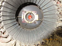
There's some sort of spring-loaded clip inside that keeps the shaft in place. The green wire and the capacitor are wired through this mechanism as well, making taking the stator out nearly impossible. I've tried prying out what looks like the lever, but it's still not budging. Has anyone seen anything like this before?

1728934693233.jpeg
 
OP
H

H0w13

Member
Joined
Jul 16, 2021
Messages
21
Location
NJ
I think I'll just cut my losses and clean what I can get to. Getting the shaft out might be more of a major surgery than I'm prepared for.
 

FrankLee

Well-known member
Joined
Sep 13, 2010
Messages
3,617
Location
seMI, 48317
There's some sort of spring-loaded clip inside that keeps the shaft in place.
That is one of the two centrifugal weights. They swing out when the motor reaches a certain rpm and opens the capacitor circuit.
If you zoom in on my photo, you'll see that my motor has the same style of weights.

Under that disk is the switch. The bearing should pass through the switch.

You're so close.

Did you remove that screw on the end cap? How long is it?
img_5329-jpg.2199454
 

FrankLee

Well-known member
Joined
Sep 13, 2010
Messages
3,617
Location
seMI, 48317
You should be able to gently lift that disk, it's spring loaded, and get a peek at the switch ring and the inboard side of the bearing.
 
OP
H

H0w13

Member
Joined
Jul 16, 2021
Messages
21
Location
NJ
Well, RIP this motor (gory photo below).

The screw on the end cap was very short, maybe 3/8" or smaller. It was just plugging up the hole for oil/grease.

The shaft was absolutely not coming out. I wasn't able to get anything under the disc with enough leverage to lift it, and I suspect there was something misaligned/jammed/just not right with the mechanism that led to it's catastrophic failure.

I took BeerHippie's advice and squirted some CRC contact cleaner down in there and called it a day. I already had repainted the top cap and the collar and it was looking nice. I figured I would paint the bottom cap once everything was back together to avoid spraying any of the internals that I couldn't remove.

Unfortunately, as I was tightening the nuts on the four threaded rods that pass through the motor, there was a sudden BANG and the motor jolted. I thought at first that this was just the collar snapping back into place, but suddenly the shaft was completely stuck. Even after taking everything apart again, I couldn't spin it even with pliers.

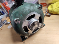
I took a look at the back of the motor, and saw this:
IMG_20241021_202203885.jpg

I have truly no idea how this could have happened just by tightening the nuts that hold everything together. I was even tightening them all gradually in an X pattern so that the force would be fairly even as the housing came back together. Something internally must have been very misaligned or perhaps something foreign was jammed in the starter switch that I couldn't see or get to.

In any case, time to try and source a replacement motor...
 

FrankLee

Well-known member
Joined
Sep 13, 2010
Messages
3,617
Location
seMI, 48317
That really *****.

That's what I was expecting with that screw. You did not replace or remove the one bearing, correct?

Did you take it apart again to figure it out?

My swag is that the spring washer was out of place and jammed between the outer race of the bearing and the edge of its bore in the cap. The rotor assembly was then pushed through the other end cap. Regardless, some forensic analysis should reveal the cause of death.
 
Last edited:
OP
H

H0w13

Member
Joined
Jul 16, 2021
Messages
21
Location
NJ
That really *****.

That's what I was expecting with that screw. You did not replace or remove the one bearing, correct?

Did you take it apart again to figure it out?

My swag is that the spring washer was out of place and jammed between the outer race of the bearing and the edge of its bore in the cap. The rotor assembly was then pushed through the other end cap. Regardless, some forensic analysis should reveal the cause of death.

Yeah now that I'm not too afraid to manhandle it a bit I plan on taking it apart further to see what went wrong. Just gotta find my soldering iron so I can de-solder the capacitor.
 
OP
H

H0w13

Member
Joined
Jul 16, 2021
Messages
21
Location
NJ
Putting this to bed...

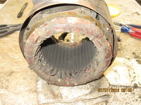
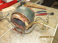
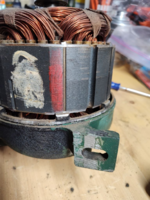
I couldn't find anything blatantly wrong once I got everything ripped apart. There was a LOT of gunk jammed under the starter switch, including about 6 small washers. My best guess is that all this garbage is what caused the higher power draw, and over time that high draw may have damaged/deformed the motor housing to the point where it finally just gave up.

The good news is that I found a new replacement motor. I'll post a separate thread on the restoration of this press at some point.
 
To avoid these ads, REGISTER NOW!
Top Bottom