To avoid these ads, REGISTER NOW!

B-Line Motor Tag Translation

7th Kahuna

Well-known member
Joined
Aug 4, 2012
Messages
1,704
Location
Los Angeles, CA
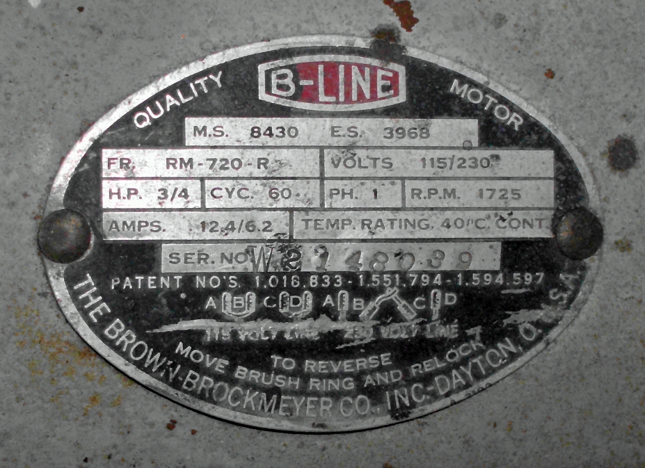
I am good with single phase electrical but a relative novice with motors. I would like to get this right the first time.

Can someone with experience please confirm my understanding of this tag. If I am reading it right, for 110v operation, I would connect A & B to Line, and C & D to neutral. For 220v operation, I would connect A to line, D to neutral and B & C together independently. Yes? Does it matter which is line and neutral? Or would that just be relative to the position of the brush ring? This motor has no visible start capacitor.

Thanks

b-line.jpg
 
To avoid these ads, REGISTER NOW!

A_Pmech

Well-known member
Joined
May 8, 2007
Messages
8,002
Location
IL
No. For 230V operation the windings are connected in series instead of in parallel. A and D are connected to the line, B&C are tied together.

It's a repulsion-induction motor. Slip ring timing adjusts the motor start direction. For AC, it doesn't matter which line is connected to which terminal.
 
OP
7

7th Kahuna

Well-known member
Joined
Aug 4, 2012
Messages
1,704
Location
Los Angeles, CA
Ok then, just to be clear, aside from there being no neutral in 230v :rolleyes:, I had it right.
Thank you.

I need to stop and read up on motor types. Repulsion-Induction has better starting torque than capacitor start motors as I recall.
 
OP
7

7th Kahuna

Well-known member
Joined
Aug 4, 2012
Messages
1,704
Location
Los Angeles, CA
If the tags are missing from the wires, could the windings be identified with a continuity tester? More specifically I suppose, does it matter which end of the winding is which? Doesn't seem like it should.
 
Last edited:
To avoid these ads, REGISTER NOW!

nehog

Well-known member
Joined
Jan 2, 2010
Messages
7,935
Location
Jaffrey, NH
If the tags are missing from the wires, could the windings be identified with a continuity tester? More specifically I suppose, does it matter which end of the winding is which? Doesn't seem like it should.

Yes, an ohm's meter will let you figure out which is which. If you get the phase wrong, however the motor won't work. Unlike some motors where you reverse (or flip) a winding, this kind of motor won't work that way.

If you want to determine phase of the windings, it is done with a simple test setup:

1. Secure a 6 to 12 volt transformer.
2. Determine which lead is which winding.
3. Connect the transformer's output to one one winding.
4. Connect the remaining winding (one lead) to one lead of the winding you connected to the transformer.
5. Connect a volt meter between the remaining unconnected lead, to the other transformer lead. If you have zero volts the leads are in phase, if you have about the transformer's voltage, they are out of phase.
6. Confirm your testing by reversing the second winding's connections and again measure the voltage.
 

Attachments

  • Motor Test.png
    Motor Test.png
    8.6 KB · Views: 22
OP
7

7th Kahuna

Well-known member
Joined
Aug 4, 2012
Messages
1,704
Location
Los Angeles, CA
Yes, an ohm's meter will let you figure out which is which. If you get the phase wrong, however the motor won't work. Unlike some motors where you reverse (or flip) a winding, this kind of motor won't work that way.

Thanks nehog. I think I will give it a try even if all the tags are still there. I'd like to get more comfortable with such things. :thumbup:
 

MTW

Well-known member
Joined
Aug 6, 2013
Messages
294
Location
SE Michigan
So my question for an induction repulsion motor, should the windings be in phase or out of phase to work properly?
MTW Ω
 
To avoid these ads, REGISTER NOW!
Top Bottom