astroracer
Well-known member
I am going to start a build thread on my Astro Van. I call it Bad Ast. It is being built in the Pro Touring style and is finishing up it's 2nd year under construction. I hope to have it drivable this summer...
I will try to catch you up on some of the more interesting build aspects. Here are a couple of posts from where it stands today.
Mel is a good friend of mine and has been involved in the build from day one. Without his help and knowledge the van would NOT be as far along as it is. I owe him a lot and appreciate his time.
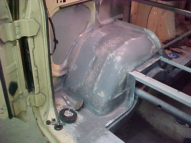
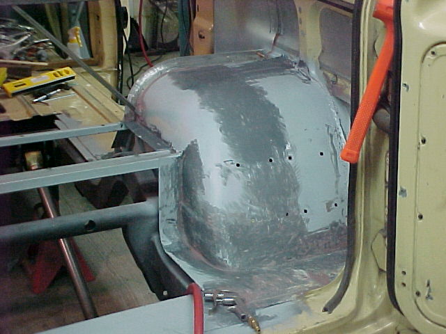
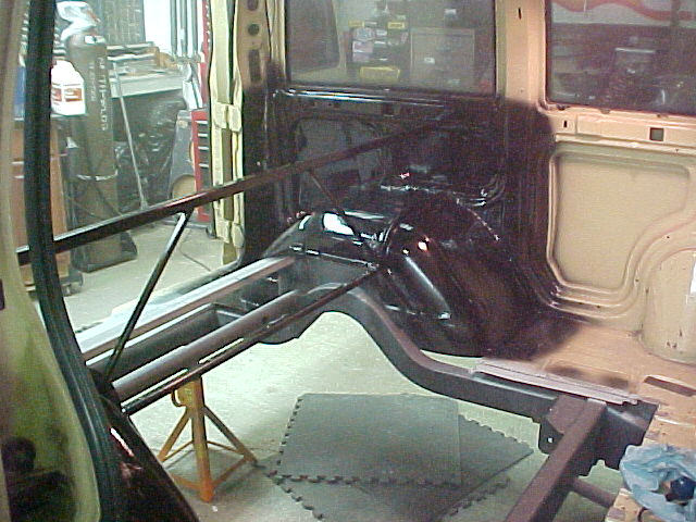
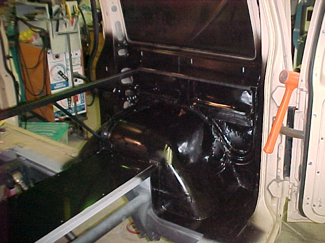
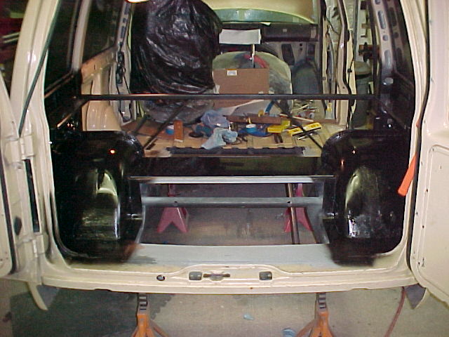
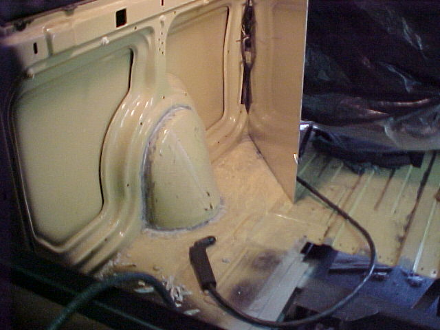
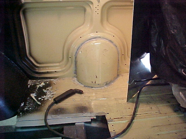
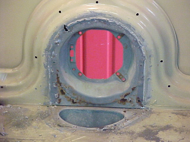
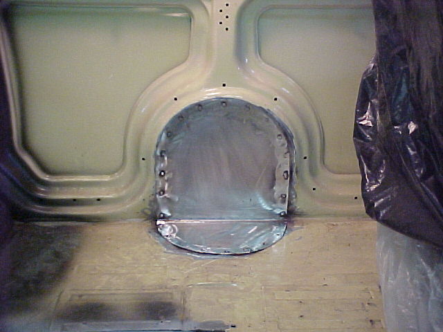
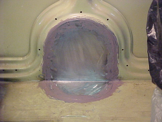
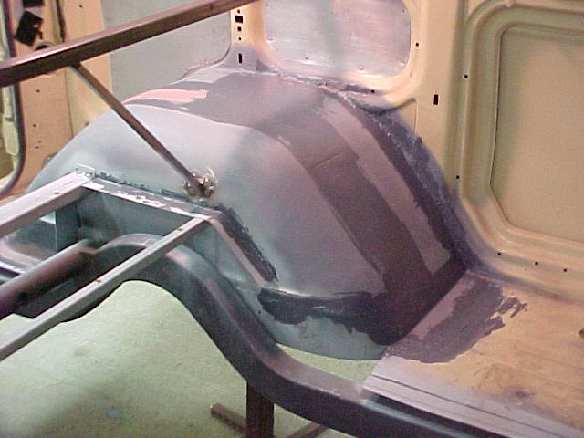
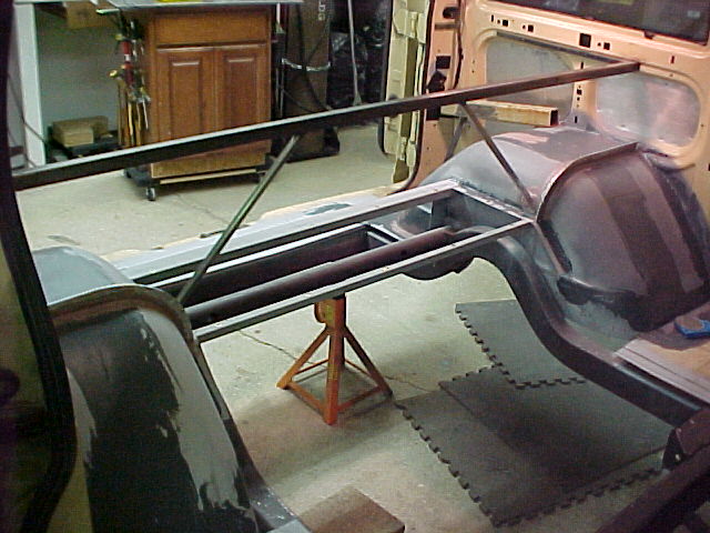
Last weekend Mel and I worked on the rear enclosure. I spent some time spreading seam sealer on the tubs and getting all of the joints packed. This is messy stuff.

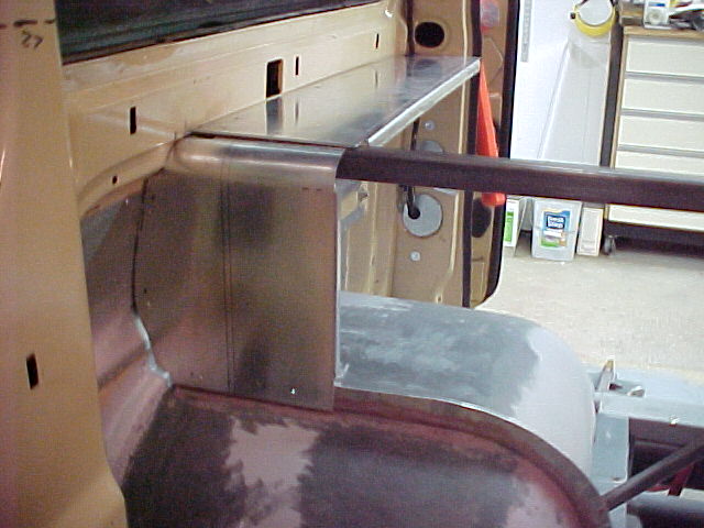
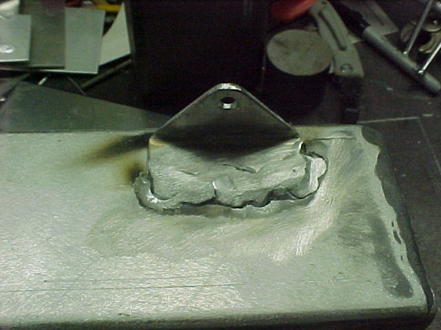
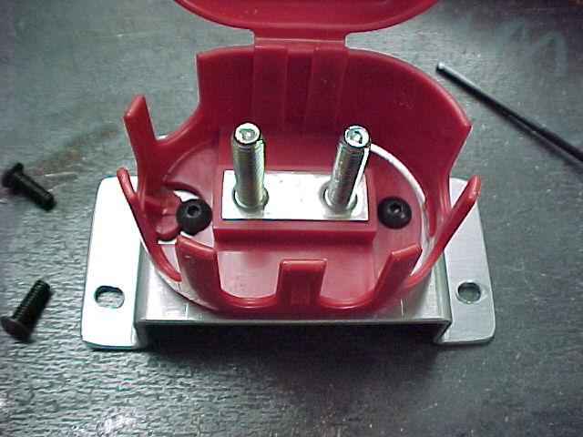
We also made up some flanges to rivet to the tubs to carry the bottom of the front enclosure panel.

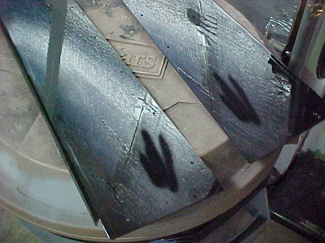
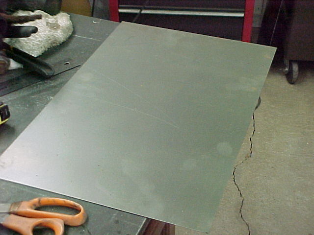
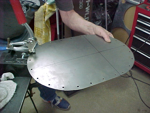
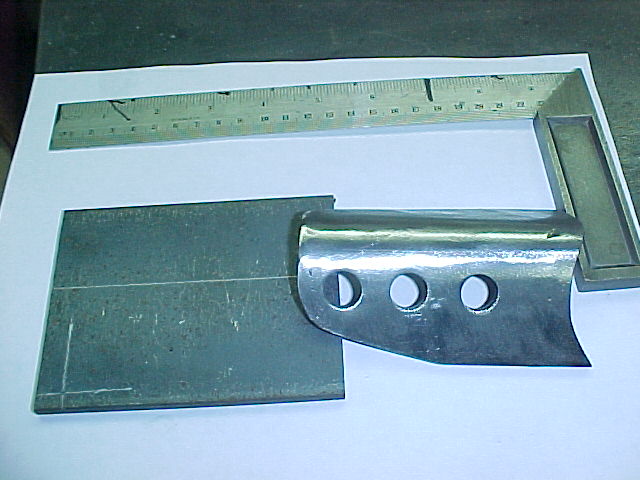
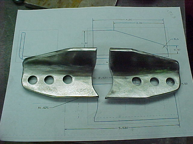
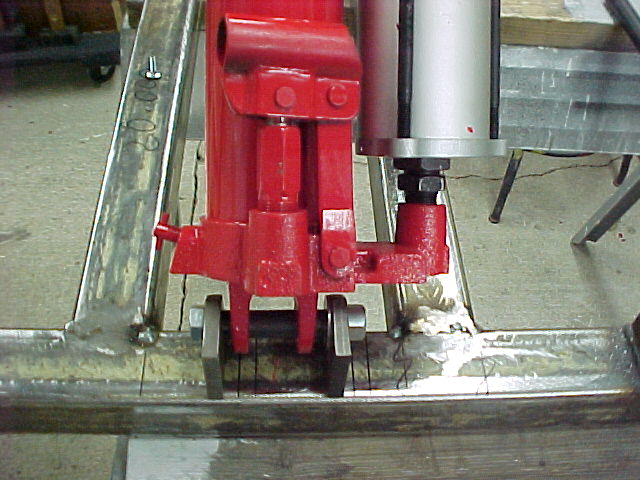
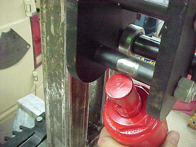
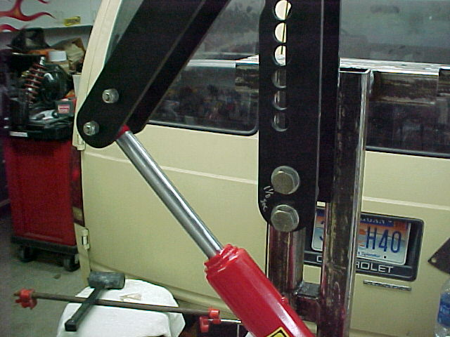
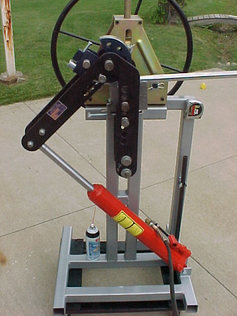
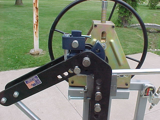
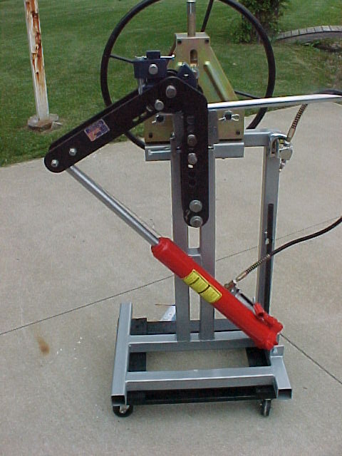
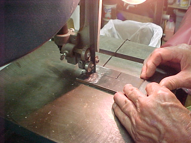
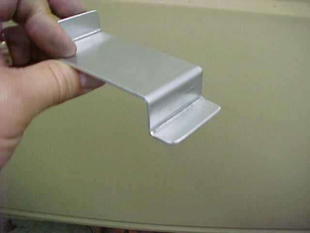
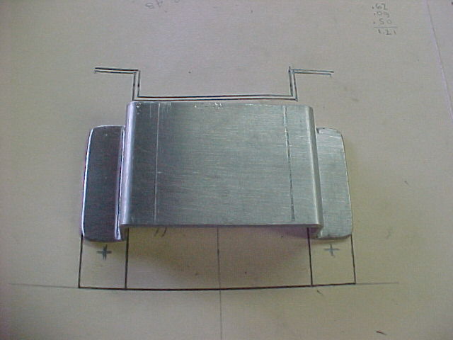
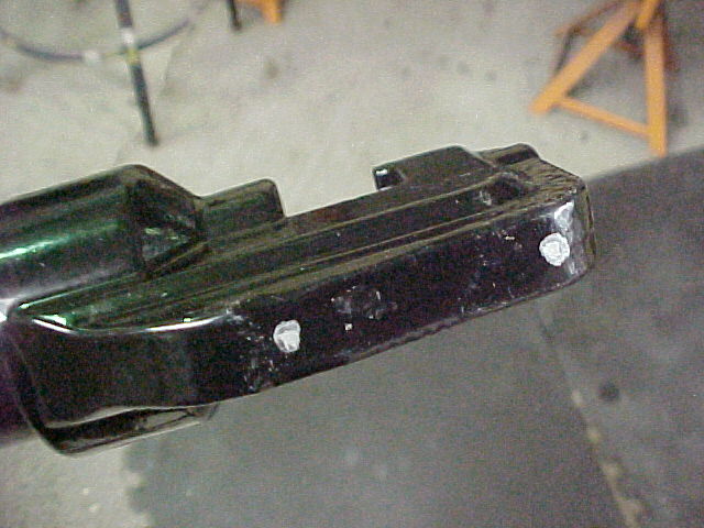
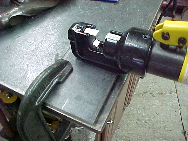
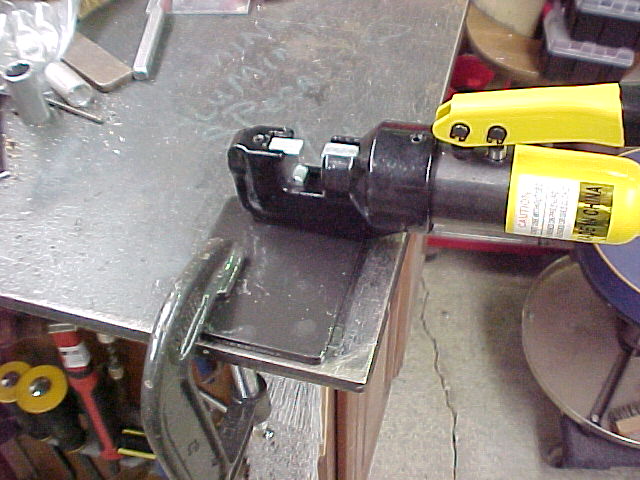
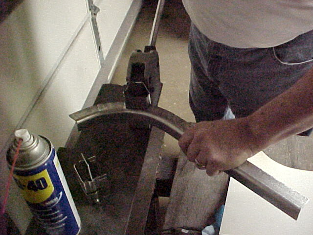
We made these out of .090 aluminum sheet. Bent them up on the 3 n 1 and ran them thru the stretcher dies to make the curve.
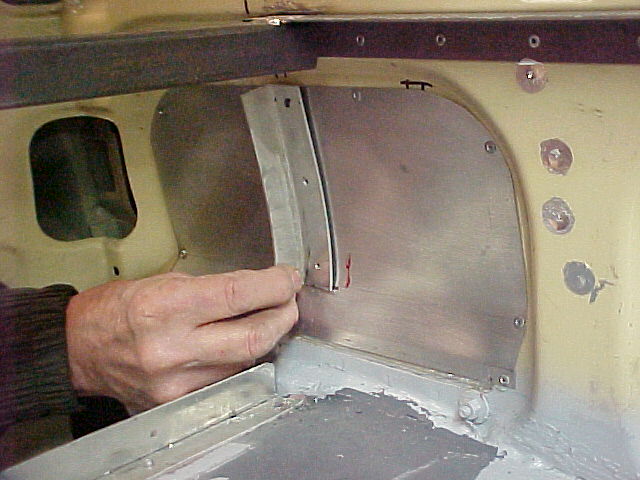
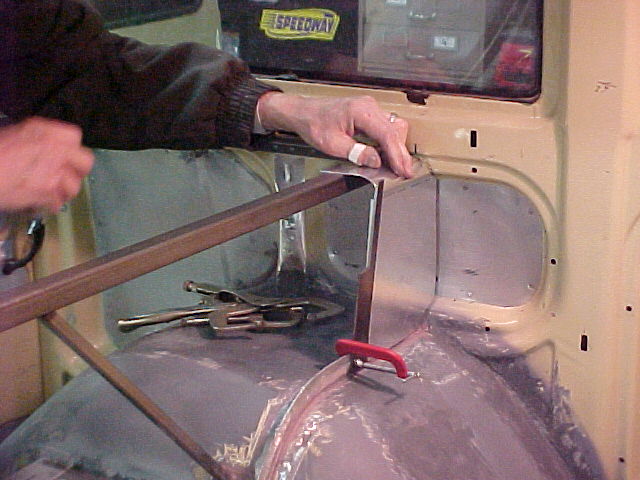
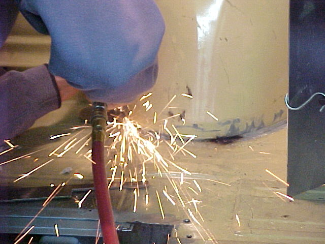
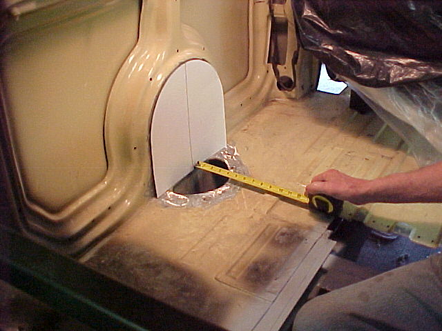
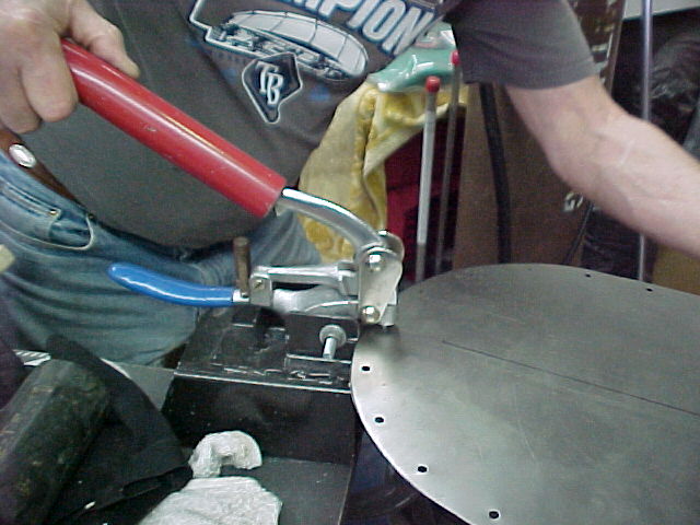
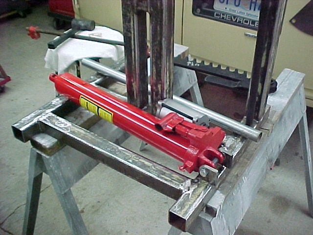
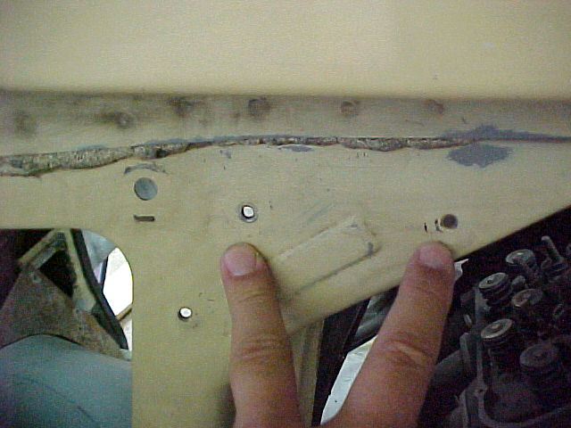
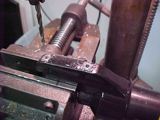
Me workin' hard...
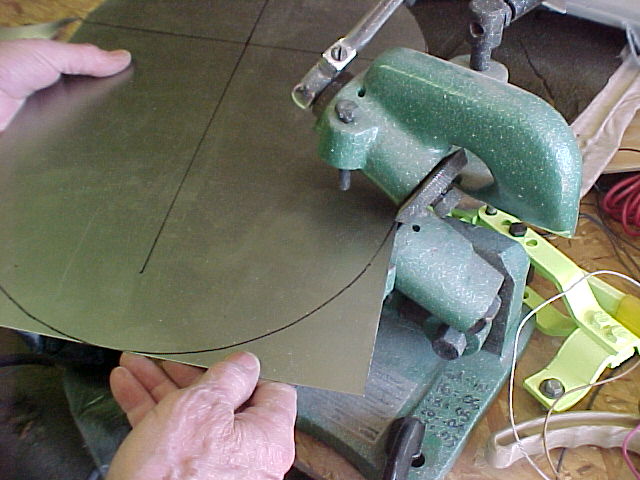
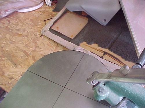
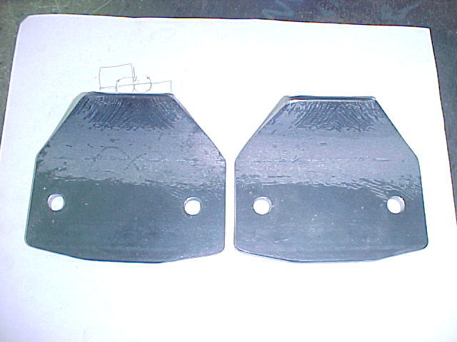
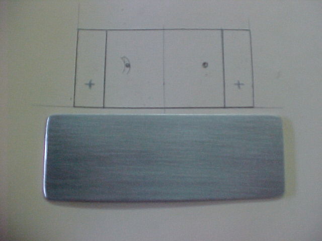
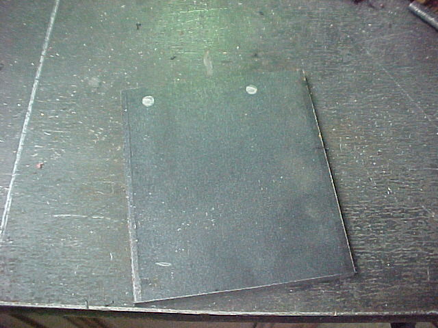
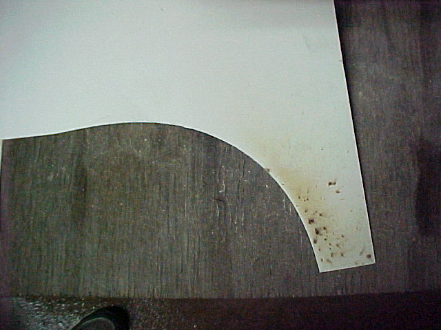
The template...
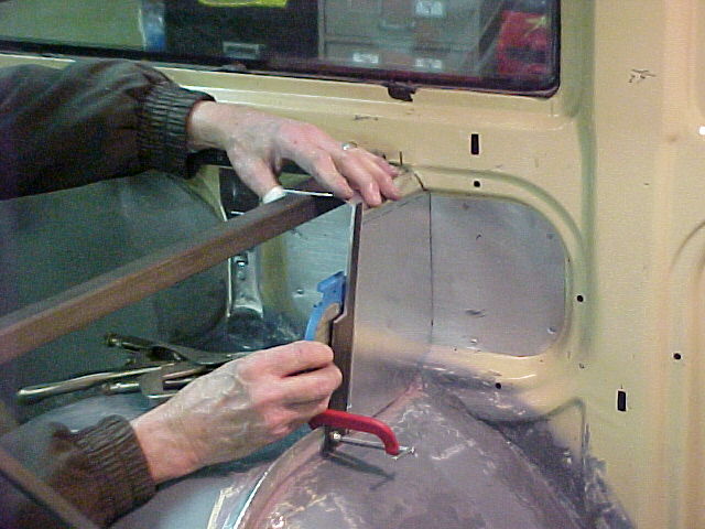
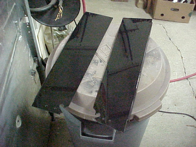
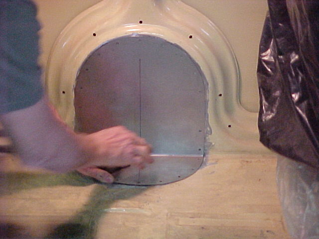
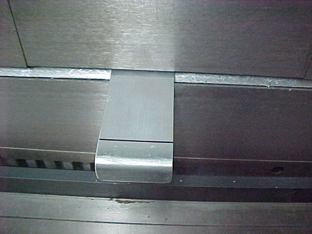
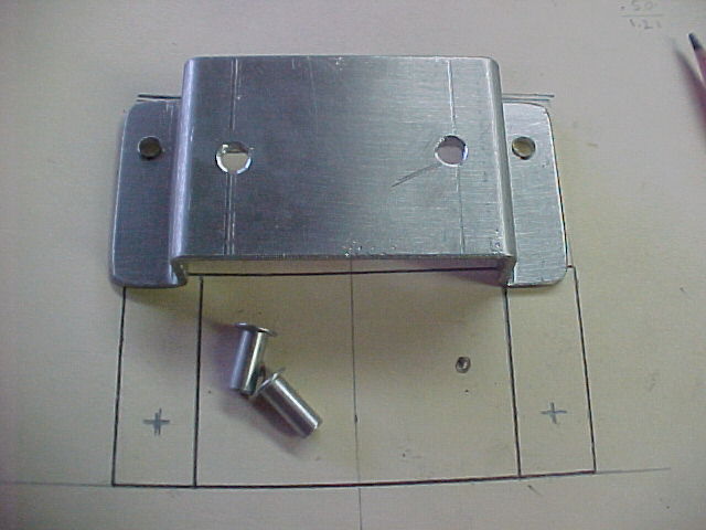
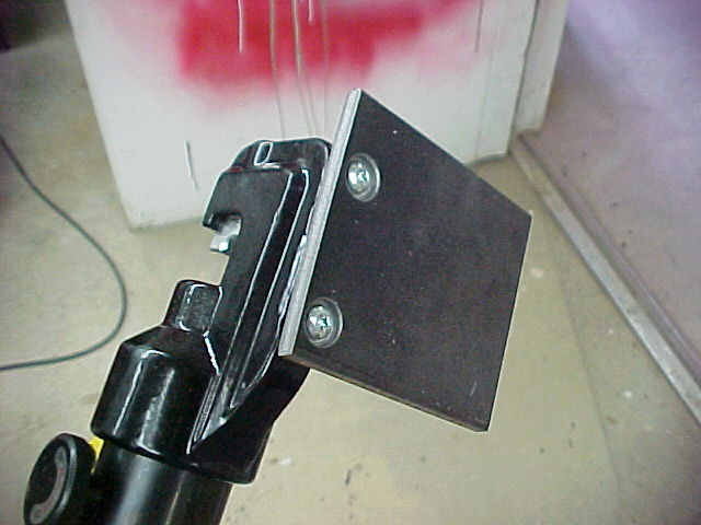
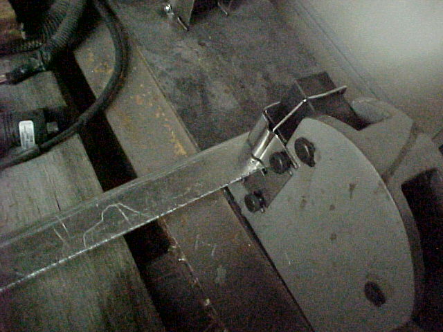
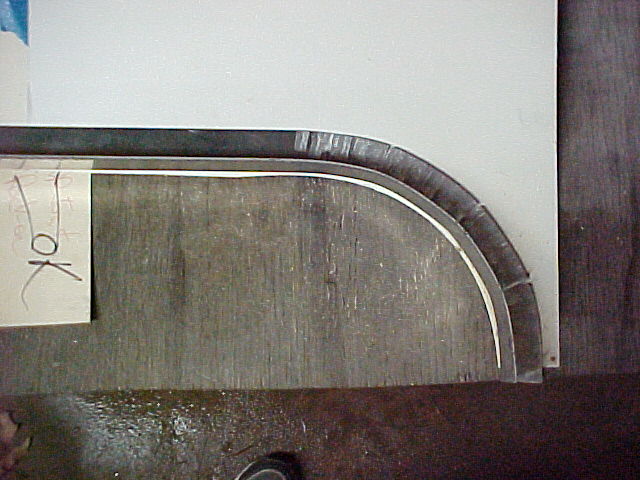
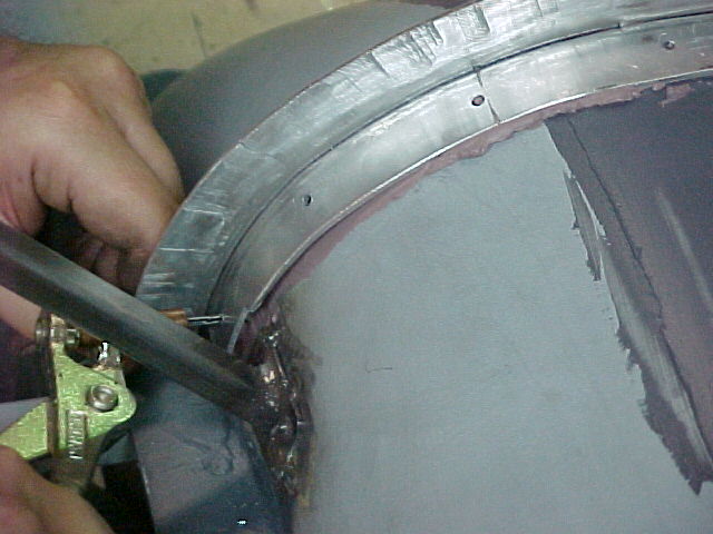
The fit...
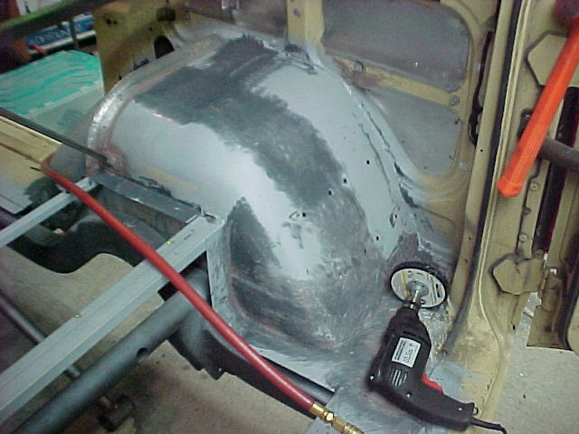
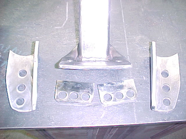
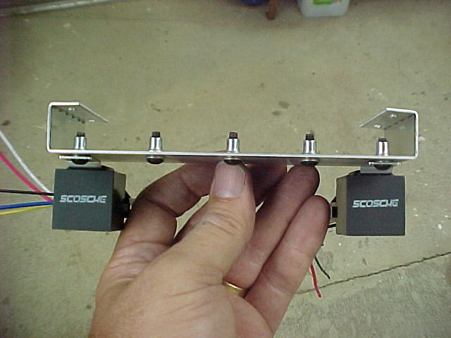
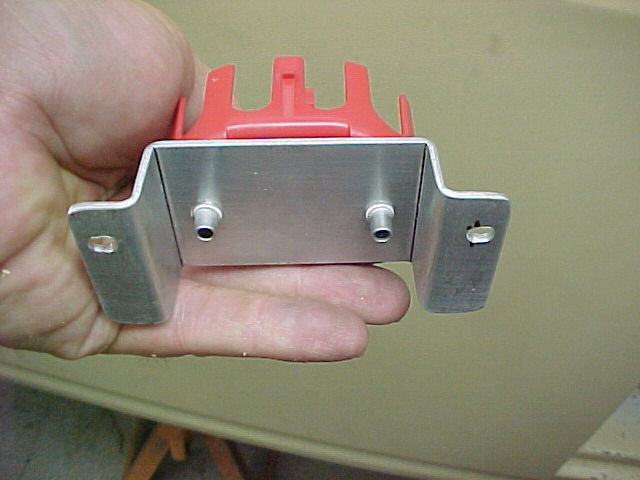
The final product...
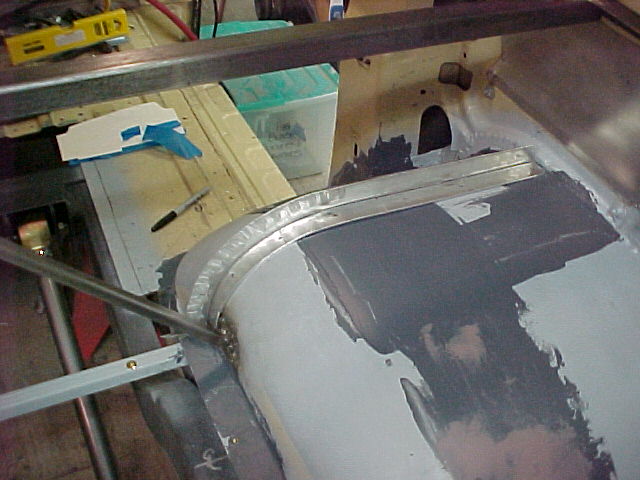
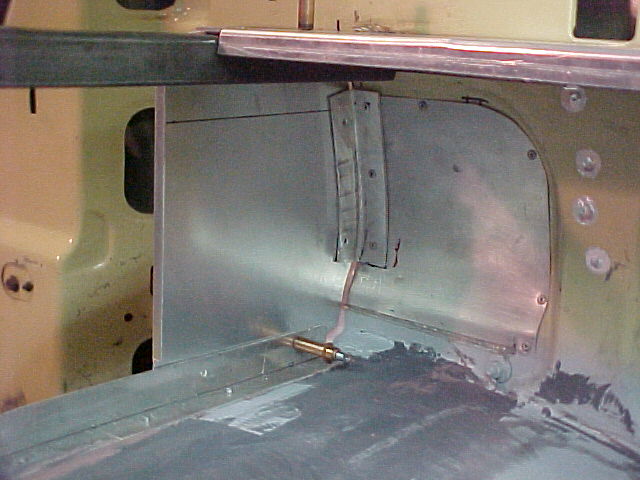
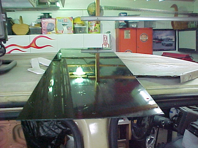
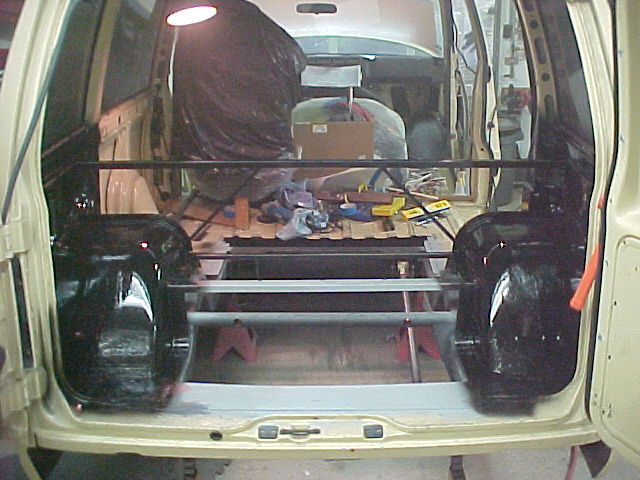
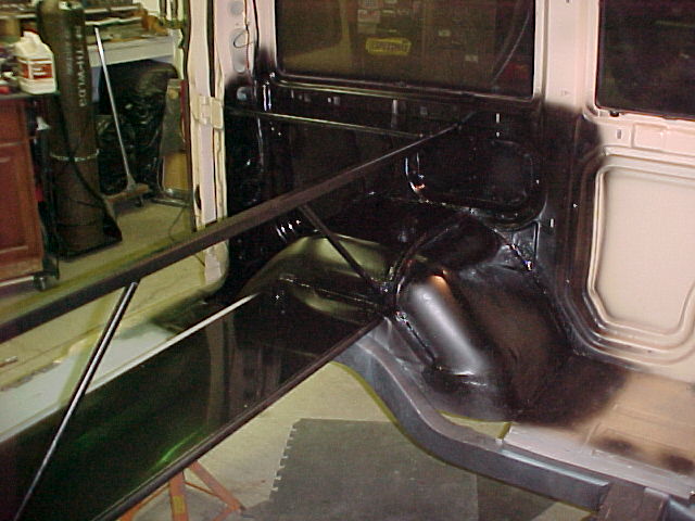
We got both sides in, seam sealed and riveted...
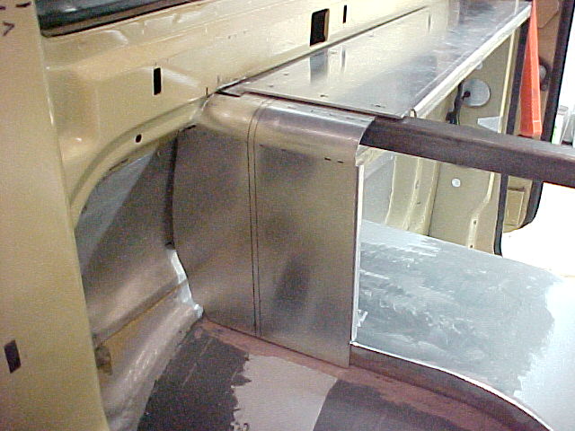
Trial fitting with a few clecoes
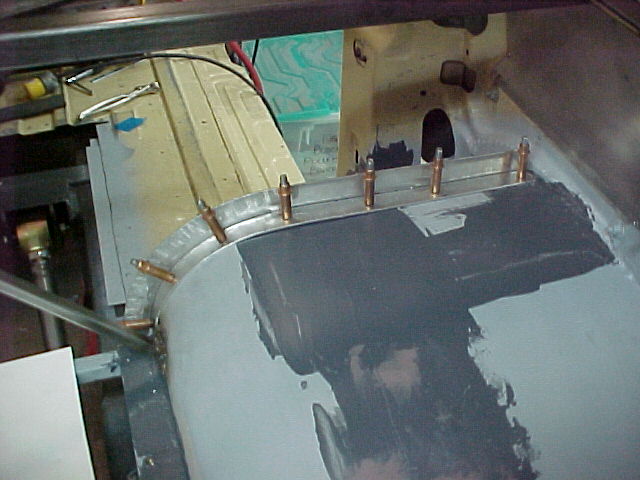
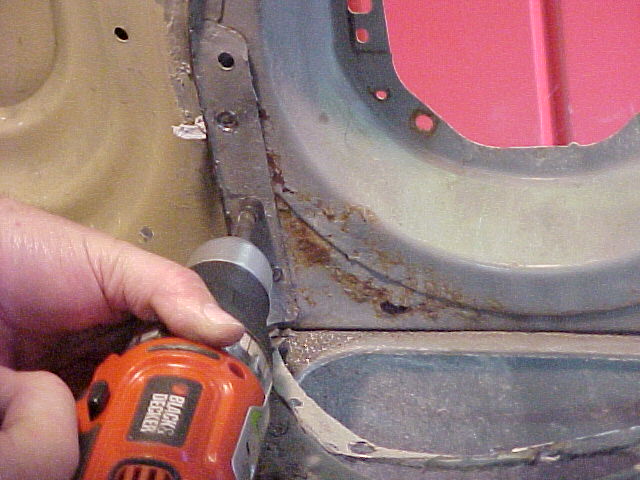
Setting them in place with a smear of seam sealer underneath. This is a clecoe going in prior to riveting.
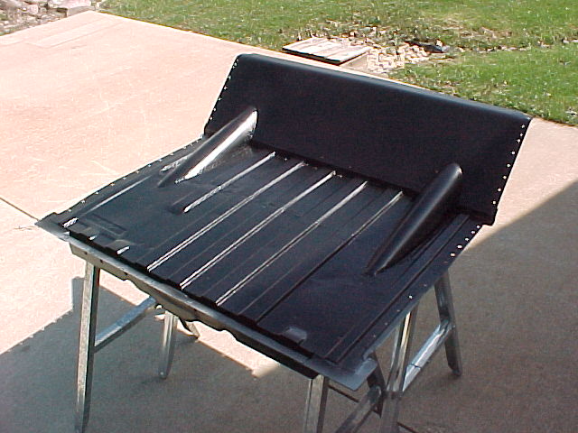
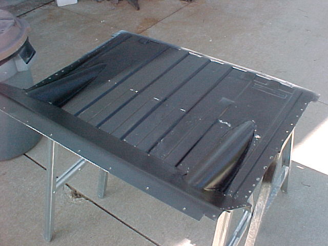
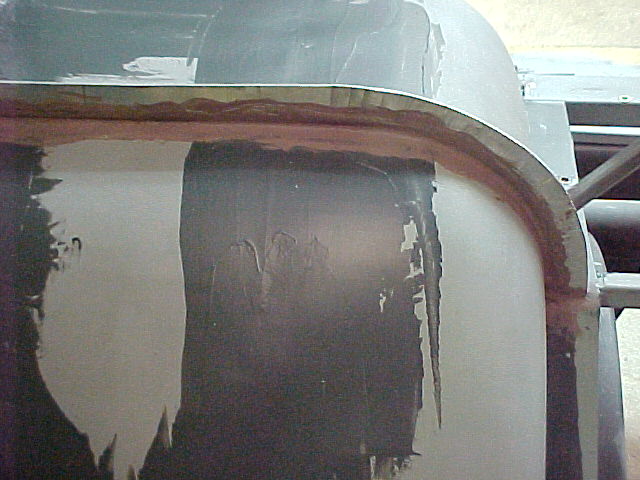
The passenger side from the front.
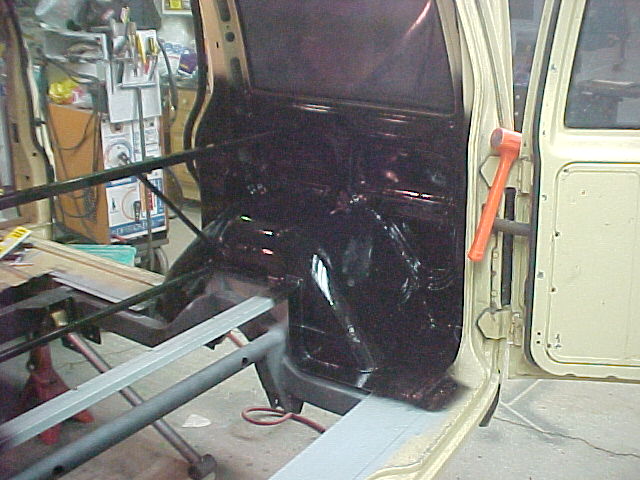
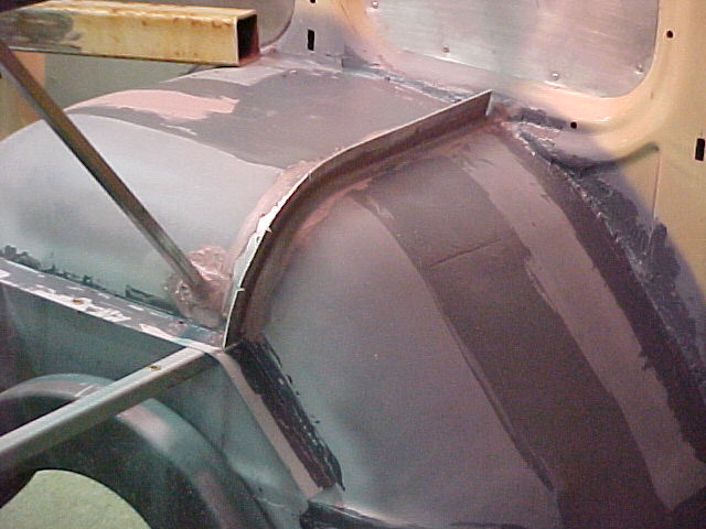
The drivers side.
Had a good day in the shop. Got a lot done and, at this point, I was hoping to be painting this stuff next weekend...
Thanks for looking and if you have any questions just ask...
Mark
I will try to catch you up on some of the more interesting build aspects. Here are a couple of posts from where it stands today.
Mel is a good friend of mine and has been involved in the build from day one. Without his help and knowledge the van would NOT be as far along as it is. I owe him a lot and appreciate his time.
Last weekend Mel and I worked on the rear enclosure. I spent some time spreading seam sealer on the tubs and getting all of the joints packed. This is messy stuff.
We also made up some flanges to rivet to the tubs to carry the bottom of the front enclosure panel.
We made these out of .090 aluminum sheet. Bent them up on the 3 n 1 and ran them thru the stretcher dies to make the curve.
Me workin' hard...
The template...
The fit...
The final product...
We got both sides in, seam sealed and riveted...
Trial fitting with a few clecoes
Setting them in place with a smear of seam sealer underneath. This is a clecoe going in prior to riveting.
The passenger side from the front.
The drivers side.
Had a good day in the shop. Got a lot done and, at this point, I was hoping to be painting this stuff next weekend...
Thanks for looking and if you have any questions just ask...
Mark
Last edited: