To avoid these ads, REGISTER NOW!

Band Saw Grinder, Wiring

Iseman

Well-known member
Joined
Dec 5, 2008
Messages
48
Location
Kerrville, TX
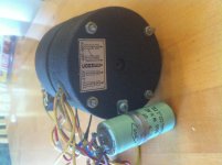
I'm hoping for the electrical motor experts to give me some guidance. I'm lost in the wiring of the grinder motor on my band saw refurbishment. It's currently wired for 3 phase 220. Everything works except the grinder. I look at the label on the motor it shows L1 1-3-5, L2 2-4-6. It is a 6 wire motor. I've attached a diagram (excuse my drawing) of the current wiring. Does this look right? It's a 1979 Jet VBS, with blade welder and can run off 220 or 480 3PH. I don't think I can get the electrical schematics for the saw, Jet no longer supports it. I'd sure appreciate some guidance and "Thanks in Advance" for any help.
 

Attachments

  • IMG_0811.jpg
    IMG_0811.jpg
    151.4 KB · Views: 34
  • Grinder.jpg
    Grinder.jpg
    42.6 KB · Views: 34
Last edited:
To avoid these ads, REGISTER NOW!

nehog

Well-known member
Joined
Jan 2, 2010
Messages
7,935
Location
Jaffrey, NH
diagram and photo imply single phase, not three phase. Can you post a picture of the motor's main specification plate?

Also the photo's wiring instructions don't match the schematic you have either.
 
OP
I

Iseman

Well-known member
Joined
Dec 5, 2008
Messages
48
Location
Kerrville, TX
The data plate in the picture is the only plate on the motor. I agree, the diagram is not the same as the plate. This is the way it was wired when I got it, but it doesn't work. The band saw is wired for 3ph and taps the L1, L2 for the welder and the grinder motor. I checked the capacitor and it checks good. I swapped lead 5 and 6 on the motor and still same results. I'm kind of an amateur on these so I'm trying to get some guidance from some of the experts from GJ, Thanks again!!
 

930dreamer

Super Moderator
Staff member
Joined
Oct 7, 2009
Messages
22,943
Location
Amarillo,TX and Stinnett,TX
No expert here, but three phase motors don't use capacitors do they? Is there an L1,L2,L3?
240 VAC Delta Connection
9
Remove all electrical power from circuit.

10
Remove motor electrical connection box cover.

11
Identify all power wires. The 240 VAC will have a black, red and blue wire for the power supply. Each identified as L1, L2 and L3 respectively. All motor wires will remain the same.

12
Connect the wires in the following manner. Attach L1 to T1 and T6. Connect L2 to T2 and T4. Secure L3 to T3 and T5. Twist the three separate connections, one a time, with the wire pliers. Cover with three separate wire nuts. Protect against moisture with black electrical tape.

13
Fold wires back inside motor electrical box. Replace cover. Turn on electrical power. Test rotation. Interchange any two main power leads, L1 and L3, if motor runs backwards.


Read more : http://www.ehow.com/how_6858346_wire-three-phase-electric-motor.html
 
Last edited:
OP
I

Iseman

Well-known member
Joined
Dec 5, 2008
Messages
48
Location
Kerrville, TX
930Dreamer, The main motor is 230v 3Ph motor and is appropriately wired. There is a wire junction box that taps 2 legs of the 3 phase wiring that runs the blade welder and grinder. If you look in the picture the grinder motor has a label for wiring 220-230 or 480. The small tube is labeled "Capacitor .5 UF.
 
To avoid these ads, REGISTER NOW!

G_P

Well-known member
Joined
Jul 11, 2010
Messages
7,135
Location
Central CT
Does the motor hum? The cap could be bad. If it does not hum. start checking resistance of the windings. The motor may just be burned up or have a broken wire inside.
 
OP
I

Iseman

Well-known member
Joined
Dec 5, 2008
Messages
48
Location
Kerrville, TX
GP, the motor makes no noises. I did check the capacitor with my analog ohm meter. I think your right about the motor being internally shorted. This afternoon I split the motor and it looks like it has been overheated. I also rang the leads and found 1,3,5, and 6 all ring shorted together. 4 and 2 ring open. If I understand the hierarchy correctly they should ring out in pairs. May look more at it tomorrow.
 
To avoid these ads, REGISTER NOW!
Top Bottom