To avoid these ads, REGISTER NOW!

Bench PSU from battery charger/jump starter?

skeer

Well-known member
Joined
Sep 14, 2021
Messages
1,049
Location
Standish, MI Area
I like to reuse and/or repurpose… it is known. So don’t flame me too much for this idea, lol.

An older Crafstman 6/12v battery charger and jump starter, the ones prolly from the 80-90’s on wheels.

An old Heathkit Battery Replacer enclosure.

I want to combine the two, I’m not remotely as awesome at electronics as most of you folks but I am pretty certain of a couple things: One is that it’s overkill. And two that charger circuits like this are electrically noisy.

Item one, yeah that doesn’t matter to me since I want to spend as little money as possible plus you can never have too much, yeah? Item two, while I’m not running medical or precision equipment off this I don’t want a cancer generating EM field either. So there must be ways to clean it up.. capacitors, coils, etc.

I’ll post more details with parts later but the desired result is a supply that can provide up to say 15 amps, and a range of 6 to 36v.
 
To avoid these ads, REGISTER NOW!

dogdog

Well-known member
Joined
Nov 15, 2011
Messages
12,711
yes you can...

dependents on what type of transformer it is inside you can convert it to an unregulated power supply or .... converted it to unregulated power then ebay and buy a dc to dc voltage regulator and make a regulated CC/CV power supply out of it.

But then again a power supply doesn't cost much more, just no fun.

open it up and start by checking out what type of transformer you have. like a regular transformer with two secondary leads. transformer with center tap 3 leads , or one of those weird transformer with multiple tap outputs. ... the HF one is just a center tap output transformer.

then look up your FullWaveBridge rectifier you need... plenty of calculator for ripple current that you can look up for filter capacitor.
 

whateg01

Well-known member
Joined
Mar 13, 2006
Messages
11,876
Location
doo dah, kansas, usa
It's probably just a transformer with a rectifier already. If that's the case there probably won't be much noise, just a 60 or 120hz hum. What voltage it voltages do you think you'll want to get out of it?
 

theoldwizard1

Well-known member
Joined
Feb 22, 2011
Messages
43,550
Location
SE MI
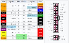
Old PC (ATX) power supply. Clean 12V and 5V. People are always throwing them away. Not sure how much current of the +12V line. Jumper pin 16 (green wire) to ground to turn it ON.

Capture.jpg

It you just want 12V, buy a used Dell DA-2 power brick (18A). I got one off of eBay for $25. Cut off the connector. White wires (3) are +12V, black (3) are ground. Obviously connect all 3 white and all 3 black together. Jump/switch the blue wire to ground to turn it ON. (Ignore the red wire.)

capture1.jpg


These voltage should be "clean". If you add a boost/buck converter, the output might be a bit noisy. (They use a high frequency switcher to make the output voltages. Only an issue for sensitive electronics.)
 
Last edited:

theoldwizard1

Well-known member
Joined
Feb 22, 2011
Messages
43,550
Location
SE MI
So there must be ways to clean it up.. capacitors, coils, etc.
The classic circuit is call a "Pi Filter" (because the schematic looks like 𝝅, 2 capacitor and a coil) or a low pass filter.

There are Pi filer calculators on line.
 
OP
S

skeer

Well-known member
Joined
Sep 14, 2021
Messages
1,049
Location
Standish, MI Area
yes you can...

dependents on what type of transformer it is inside you can convert it to an unregulated power supply or .... converted it to unregulated power then ebay and buy a dc to dc voltage regulator and make a regulated CC/CV power supply out of it.

But then again a power supply doesn't cost much more, just no fun.

open it up and start by checking out what type of transformer you have. like a regular transformer with two secondary leads. transformer with center tap 3 leads , or one of those weird transformer with multiple tap outputs. ... the HF one is just a center tap output transformer.

then look up your FullWaveBridge rectifier you need... plenty of calculator for ripple current that you can look up for filter capacitor.
Can you define, regulated versus unregulated?
 
OP
S

skeer

Well-known member
Joined
Sep 14, 2021
Messages
1,049
Location
Standish, MI Area
Old PC (ATX) power supply. Clean 12V and 5V. People are always throwing them away. Not sure how much current of the +12V line. Jumper pin 16 (green wire) to ground to turn it ON.

Capture.jpg

It you just want 12V, buy a used Dell DA-2 power brick (18A). I got one off of eBay for $25. Cut off the connector. White wires (3) are +12V, black (3) are ground. Obviously connect all 3 white and all 3 black together. Jump/switch the blue wire to ground to turn it ON. (Ignore the red wire.)

capture1.jpg


These voltage should be "clean". If you add a boost/buck converter, the output might be a bit noisy. (They use a high frequency switcher to make the output voltages. Only an issue for sensitive electronics.)
I almost went this route, but I’ve two concerns: can a typical atx psu handle say a legit 15+ amp load on the 12v rail? Second the only one I have that I could sacrifice is a measly 350watts.
 
OP
S

skeer

Well-known member
Joined
Sep 14, 2021
Messages
1,049
Location
Standish, MI Area
It's probably just a transformer with a rectifier already. If that's the case there probably won't be much noise, just a 60 or 120hz hum. What voltage it voltages do you think you'll want to get out of it?
I’d love to get say sub-12, 12, then perhaps 24, and 36. Potentially variable. That’s the pipe bream anyway.
 

theoldwizard1

Well-known member
Joined
Feb 22, 2011
Messages
43,550
Location
SE MI
I almost went this route, but I’ve two concerns: can a typical atx psu handle say a legit 15+ amp load on the 12v rail? Second the only one I have that I could sacrifice is a measly 350watts.
Not sure about an ATX supply, but my Dell DA-2 can ! I couldn't beat the price !!

I am pretty certain the red wire is a voltage sense wire. If so, connect it to the +12V wires.
 

dogdog

Well-known member
Joined
Nov 15, 2011
Messages
12,711
Can you define, regulated versus unregulated?
I don't know if I can...
I think regulated is when your power supply can control or maintain a certain set voltage or current as output. you can have constant voltage or constant current but not both in... say its set for 2.5A constant current... your power supply will maintain that current output even if it is at cost of voltage dropping. there is more to that but I forgot. Constant voltage is that it tries to maintain the voltage level at the cost of output amp.... There is that EEVblog guy dave have a review on some of those CC/CV dc to dc regulators few years ago. He was impressed...

unregulated it's what ever voltage the transformer brings you and what ever your load takes you up to the max of that transformer till something burns, use fuse then until fuse blows... I think... not too sure.. basically it's just a transformer, diode(s) and a filtering capacitor(s) on output. no inductors. no LC anything filters for any frequency other than ripple current... you can google these. and google the formula for ripple current to calculate the filtering capacitor.

All dependents what you want that converted power supply to power.
 
OP
S

skeer

Well-known member
Joined
Sep 14, 2021
Messages
1,049
Location
Standish, MI Area
Thanks!! I appreciate that and it makes sense. I assume that even a battery charger transformer will only put out the voltage the windings allow.
 

whateg01

Well-known member
Joined
Mar 13, 2006
Messages
11,876
Location
doo dah, kansas, usa
Yes, but depending on how it's wound, you may be able to connect them in series to get more voltage or in parallel to get more current. If it's just multiple taps of the same winding that's not possible.
 
OP
S

skeer

Well-known member
Joined
Sep 14, 2021
Messages
1,049
Location
Standish, MI Area
Yes, but depending on how it's wound, you may be able to connect them in series to get more voltage or in parallel to get more current. If it's just multiple taps of the same winding that's not possible.
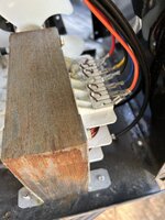
Ahh I didn’t think of that, interesting. The seventh tap on the hot primary side was unused.


Advice on mapping a t-former?
 

American Locomotive

Well-known member
Joined
Jan 8, 2017
Messages
11,137
Location
Rhode Island
I don't think that transformer is going to do what you want it to. It will be unregulated, the voltage will swing around wildly as you load and unload it, and I don't think any configuration of the primary winding taps will ever allow for 36v.

I like the idea of re-using an old Heathkit enclosure, but there are different guts you can put in it. Almost any computer power supply made in the last 15 years should be capable of at least 20A on the 12V output.
 

theoldwizard1

Well-known member
Joined
Feb 22, 2011
Messages
43,550
Location
SE MI
are you sure those are not the secondary ?
My guess is that 8 and 9 are the primary. If you can compare the wire connecting 8 and 9 to the windings it should be smaller diameter than the others.

Also, my educated guess is that one of 1 - 7 is common to all of them. Maybe 1 or maybe 7 ? Forget ohms, just do a continuity test.
 
OP
S

skeer

Well-known member
Joined
Sep 14, 2021
Messages
1,049
Location
Standish, MI Area
Nope, 8-9 are the secondary negative. I traced it all earlier.. lemme go grab a pic of that. Suffice to say the lower half is the larger gauge wire, one side is the secondary positives (4), the opposite with is secondary negative (2).

I’ll update the sheet with continuity too.
 
To avoid these ads, REGISTER NOW!
OP
S

skeer

Well-known member
Joined
Sep 14, 2021
Messages
1,049
Location
Standish, MI Area
1-7 are all connected to each other. That’s a poor way to word that, but in a continuity sense they are all connected to each other.
1-7 do not tie to 8-9 or 10-13.
IMG_0135.jpeg
 

whateg01

Well-known member
Joined
Mar 13, 2006
Messages
11,876
Location
doo dah, kansas, usa
I'm not following. In use, the primary is connected to line voltage and the secondaries are selected to provide the desired voltage. There aren't multiple primaries unless line voltage is switched between them to get the desired voltage on that one winding. I guess it could be done that way but it seems odd.
 
OP
S

skeer

Well-known member
Joined
Sep 14, 2021
Messages
1,049
Location
Standish, MI Area
I don't think that transformer is going to do what you want it to. It will be unregulated, the voltage will swing around wildly as you load and unload it, and I don't think any configuration of the primary winding taps will ever allow for 36v.

I like the idea of re-using an old Heathkit enclosure, but there are different guts you can put in it. Almost any computer power supply made in the last 15 years should be capable of at least 20A on the 12V output.
Yeah I’m now on the fence about the original idea. Number one as you pointed out it won’t allow for 36v. Number two it’s really big, I’ll have to reinforce the Heathkit to handle the weight.
 

dogdog

Well-known member
Joined
Nov 15, 2011
Messages
12,711
Maybe you can get the 12V 40AMP output from your diagram as pin 4 and 5.
 

theoldwizard1

Well-known member
Joined
Feb 22, 2011
Messages
43,550
Location
SE MI
Very confusing !!

First, on the rotary switch terminal #4 may be labeled OFF, but it is really the "common" (wiper arm) to all the terminals. It is HOT (120VAC) AT ALL TIMES ! It is just a " holding place" for the knob.

The way transformers work is based on "turn ratios". The larger/lower the number of turns between in primary and secondary controls the output voltage (1:1 would theoretically give the same output voltage as the input voltage). The primary side has multiple windings hidden inside.

The 6V windibg is 1/2 the length of any of the 12V windings. More current out required more current in. Somehow the different input connections some how make the input winding wire "thicker" or add another coil in PARALLEL to the first winding.

#4 is common to all input coil windings.

For maximum current out just wire Line to transformer terminal #6 and Neutral to #4. You will be wasting some power (to heat) if you are using less. If I under stand your picture, the 10A switch position would actually be capable of 40A !
 
Last edited:

Wrench97

Well-known member
Joined
Jun 23, 2018
Messages
12,361
Location
Southeastern Pa
I’d love to get say sub-12, 12, then perhaps 24, and 36. Potentially variable. That’s the pipe bream anyway.
The label on the supply should tell you the amperage the 12v is rated for.
The higher the wattage the higher the 12v rail is rated high end video cards can require over 50 amps of power.
 
OP
S

skeer

Well-known member
Joined
Sep 14, 2021
Messages
1,049
Location
Standish, MI Area
The label on the supply should tell you the amperage the 12v is rated for.
The higher the wattage the higher the 12v rail is rated high end video cards can require over 50 amps of power.
Well.. yeah but I was referring to voltage rather than amperage. I shoulda specified ;). The ideal though, from whatever ends up powering a shop DC supply, is to be able to test stuff like this actuator motor from it. It's a 36v, 3-ish amp pull. Or say a 24v object that might pull 8 amps. Maybe a typical 450w atx ps can do that.. IDK.
 
OP
S

skeer

Well-known member
Joined
Sep 14, 2021
Messages
1,049
Location
Standish, MI Area
Very confusing !!

First, on the rotary switch terminal #4 may be labeled OFF, but it is really the "common" (wiper arm) to all the terminals. It is HOT (120VAC) AT ALL TIMES ! It is just a " holding place" for the knob.

The way transformers work is based on "turn ratios". The larger/lower the number of turns between in primary and secondary controls the output voltage (1:1 would theoretically give the same output voltage as the input voltage). The primary side has multiple windings hidden inside.

The 6V windibg is 1/2 the length of any of the 12V windings. More current out required more current in. Somehow the different input connections some how make the input winding wire "thicker" or add another coil in PARALLEL to the first winding.

#4 is common to all input coil windings.

For maximum current out just wire Line to transformer terminal #6 and Neutral to #4. You will be wasting some power (to heat) if you are using less. If I under stand your picture, the 10A switch position would actually be capable of 40A !
Yes I agree, I probably could have worded or explained it better though.

You are correct about rotary switch #4. At it's max setting it claims 12v @ 200A but I don;t see ever needing that much. Still wished I could somehow get at least 24v out of it but I guess it's not in the cards this time.
 

RPH

Well-known member
Joined
Dec 17, 2006
Messages
4,190
Location
Michigan Thumb
1711983625368.jpeg
This graphic shows what individual components do to the dc output. How clean do you want the power to be? That determines the filtering required.
 

theoldwizard1

Well-known member
Joined
Feb 22, 2011
Messages
43,550
Location
SE MI
1711983625368.jpeg
This graphic shows what individual components do to the dc output. How clean do you want the power to be? That determines the filtering required.
The last time I did any EE work was over 30 years ago but, if I recall, on a Pi filter, the 2 capacitor are different "styles". One is an electrolytic (polarity matters) and the other a ceramic/tantalum. It does make a difference.
 

theoldwizard1

Well-known member
Joined
Feb 22, 2011
Messages
43,550
Location
SE MI
I also found this

Disadvantages of the Pi Filter
Higher Wattage Inductor Values
Other than the RF design, High current draw through a Pi filter is not advisable since the current has to flow through the Inductor. If this load current is relatively high, then the wattage of the Inductor also increases making it bulky and expensive. Also, the high current through the inductor increases the power dissipation across the inductor resulting in poor efficiency.​
High-value Input Capacitor
Another major problem of the Pi filter is the large input capacitance value. Pi filters require high capacitance across the input which became a challenge in space-constrained applications. Also, high-value capacitors increase the cost of the design.​
 

theoldwizard1

Well-known member
Joined
Feb 22, 2011
Messages
43,550
Location
SE MI
The ideal though, from whatever ends up powering a shop DC supply, is to be able to test stuff like this actuator motor from it. It's a 36v, 3-ish amp pull. Or say a 24v object that might pull 8 amps. Maybe a typical 450w atx ps can do that.. IDK.
The only way you are going to get that voltage range and POWER is with a buck/boost converter. For that kind of power (24V x 8A is about 200W) they are not cheap.
 

Wrench97

Well-known member
Joined
Jun 23, 2018
Messages
12,361
Location
Southeastern Pa
Well.. yeah but I was referring to voltage rather than amperage. I shoulda specified ;). The ideal though, from whatever ends up powering a shop DC supply, is to be able to test stuff like this actuator motor from it. It's a 36v, 3-ish amp pull. Or say a 24v object that might pull 8 amps. Maybe a typical 450w atx ps can do that.. IDK.
No an ATX supply has 5v, 12v and 3.3v DC
 
OP
S

skeer

Well-known member
Joined
Sep 14, 2021
Messages
1,049
Location
Standish, MI Area
No an ATX supply has 5v, 12v and 3.3v DC
Right right.. some even have multiple rails for each set voltage. I have one on my desk right now that claims 3 x12v with 8, 18.5, and 18a respectively. Although I know better than to assume it could handle a full like 42-ish amp draw. But yeah the idea is to repurpose a transformer/psu from something that could ramp from say 1 to 36v, with a max amperage of like 20 (if Im dreaming) amps. Would love to find an autoformer or an old variac to throw into the Heathkit but I'm not that lucky.
 

Wrench97

Well-known member
Joined
Jun 23, 2018
Messages
12,361
Location
Southeastern Pa
Right right.. some even have multiple rails for each set voltage. I have one on my desk right now that claims 3 x12v with 8, 18.5, and 18a respectively. Although I know better than to assume it could handle a full like 42-ish amp draw. But yeah the idea is to repurpose a transformer/psu from something that could ramp from say 1 to 36v, with a max amperage of like 20 (if Im dreaming) amps. Would love to find an autoformer or an old variac to throw into the Heathkit but I'm not that lucky.
Yes but you will find they are not actually 3 separate 12v and the neg side is common, so hooking them in series will just short them out.
 
To avoid these ads, REGISTER NOW!
Top Bottom