To avoid these ads, REGISTER NOW!

Blacksmith Post Leg Vise Restoration

2oolhound

Well-known member
Joined
Dec 18, 2010
Messages
5,918
Location
BC Canada
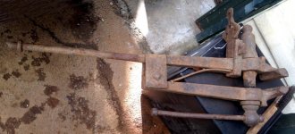
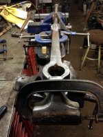
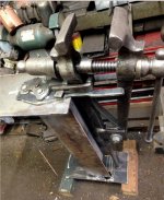
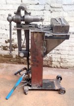
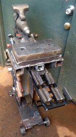
I scored a post leg vise recently from a junk dealer. I've wanted one of these for about 50 years and finally pulled the trigger.

attachment.php


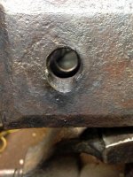
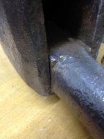
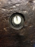
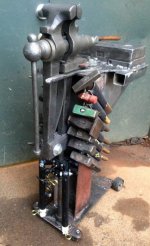
This one's a 5". I talked the seller down to $40 because there was so much slop in it. I've since learned the dynamic jaw and main screw float so they don't absorb any shock from pounding on the vise. All that force goes straight down the leg to the ground. That accounts for some of the slop and misalignment I felt in the jaws. After a bit of cleaning up I found the makers stamp. It's an I. Nash and Sons of Stourbridge Eng. Isaac Nash died in 1877 or 8 but the company moved to Stourbridge in 1896 and still going strong apparently.

attachment.php


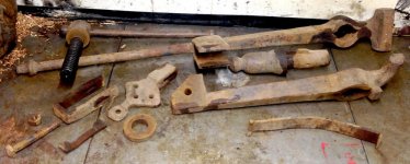
There was a similar thread here a month or so back but danged if I could find it. That thread inspired me to clean this one up too instead of just using it as is.

attachment.php


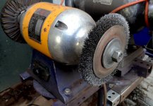
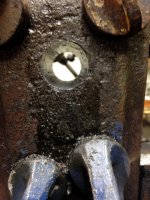
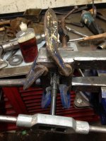
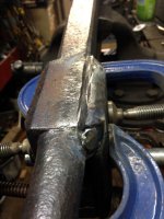
I usually attack rust with a vinegar bath but this vise would need a special tank so I just went at it with a wire brush mounted on a 3/4 hp bench grinder.

attachment.php


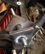
The tight corners and crevices were gotten with a knotted wheel or cup brush on a small angle grinder.

attachment.php
 

Attachments

  • BlksmithPostLegViseSm_3550.jpg
    BlksmithPostLegViseSm_3550.jpg
    76.7 KB · Views: 338
  • BlksmithPostLegViseSm_3555.jpg
    BlksmithPostLegViseSm_3555.jpg
    103 KB · Views: 338
  • BlksmithPostLegViseSm_4924.jpg
    BlksmithPostLegViseSm_4924.jpg
    73.6 KB · Views: 338
  • BlksmithPostLegViseSm_4927.jpg
    BlksmithPostLegViseSm_4927.jpg
    57.3 KB · Views: 333
  • BlksmithPostLegViseSm_4938.jpg
    BlksmithPostLegViseSm_4938.jpg
    61.6 KB · Views: 332
To avoid these ads, REGISTER NOW!
OP
2

2oolhound

Well-known member
Joined
Dec 18, 2010
Messages
5,918
Location
BC Canada
Now for some bad news. I discovered the cause of a lot of the slop. The bolt holding the dynamic jaw at the pivot point was a 5/8" bolt but the hole is a 3/4". I don't know how long the vise was used like this but it caused some bad damage and it must have been very wonky. The 2 plates that were forge welded to the main leg for the pivot point were spread and one of the plates was cracking at the weld along the sides. The back had a faint line along the weld too. (that faint line top right of the 3rd photo is a faint crack starting).

attachment.php


attachment.php


attachment.php


I decided to leave the back forged weld alone as it was mostly good and just weld the top and bottom ends along the side of the leg. I was glad to have bayonet mounts every 12" along my bench which allowed me to position 2 vises 2' apart to hold the awkward leg vise.

attachment.php


I bolted the dynamic jaw in position with large washers to hold the plates snuggly in position, heated the leg and plate to a dull red and welded the top and bottom ends of the plate to the post.

Next I decided to weld the hole in the plate where it had been elongated by the wrong bolt.

attachment.php


My plan was to heat the plate again and use 1/16" rod to tack a light bead on the inside right up to where the damage ended. Then I could safely add 1/8" rod to the outer area without melting away any of the undeformed hole further in. I also got a great idea to take a 3/4" bolt and taper it on the lathe and cut some sharp grooves in it and then quickly drive it through the fresh weld to clear out the excess fresh weld.

attachment.php


This reamer worked perfectly cleaning out the hole so a normal bolt would fit and it eliminated any hand filing or drilling of the cumbersome leg.

Next I laid in the 1/8" rod to fill in the outer area of the damaged hole. I was so proud of my brilliant idea to make the reamer from the bolt and drive it through the hot weld I was singing as I worked. I don't even know the name of the song but it goes like this:
dumb dumb dumb dumb dumb
dumb ditty dumb dumb dumb dumb dumb
dumb ditty duuuum
Driving the bolt through the big weld was going good but it was slowing down so I grabbed a 4 lb. hammer and started wailing on it still singing the song in my head Dumb dumb dumb dumb ----dumb

attachment.php


DAM! I busted the plate clean off!

.
.
.
 

Attachments

  • BlacksmithPostLegViseSm_4990.jpg
    BlacksmithPostLegViseSm_4990.jpg
    58.9 KB · Views: 304
  • BlacksmithPostLegViseSm_4983.jpg
    BlacksmithPostLegViseSm_4983.jpg
    52.1 KB · Views: 308
  • BlacksmithPostLegViseSm_4980.jpg
    BlacksmithPostLegViseSm_4980.jpg
    73.2 KB · Views: 308
  • BlacksmithPostLegViseSm_4956.jpg
    BlacksmithPostLegViseSm_4956.jpg
    66.5 KB · Views: 309
  • BlacksmithPostLegViseSm_4955.jpg
    BlacksmithPostLegViseSm_4955.jpg
    57.1 KB · Views: 311
  • BlacksmithPostLegViseSm_4954.jpg
    BlacksmithPostLegViseSm_4954.jpg
    51.8 KB · Views: 307
  • BlacksmithPostLegViseSm_4950.jpg
    BlacksmithPostLegViseSm_4950.jpg
    45.8 KB · Views: 309
Last edited:
OP
2

2oolhound

Well-known member
Joined
Dec 18, 2010
Messages
5,918
Location
BC Canada
What now Charlie Brown? I carfully fitted the plate back into position, clamped it then vee'd it out for welding.

attachment.php


Heated up again to light red and farmer welded it.

attachment.php


I peened the weld to release the tension and for looks.

attachment.php


With the pesky plate out of the way I aligned the top jaws as the dynamic jaw was 1/8" lower than the static jaw. Then I clamped it when it was even.

attachment.php


You can see the inner form of the dynamic jaw sticks out 1/16" or so on the left since aligning the jaws up top. I drilled it out to 13/16" (from 3/4") to even out the discrepancy.

attachment.php


Then I reamed out the hole to 7/8".

attachment.php


Here is the new holes reamed to 7/8" and the top jaws now both the same height.

attachment.php
 

Attachments

  • BlacksmithPostLegViseSm_5023.jpg
    BlacksmithPostLegViseSm_5023.jpg
    73.4 KB · Views: 300
  • BlacksmithPostLegViseSm_5018.jpg
    BlacksmithPostLegViseSm_5018.jpg
    63.9 KB · Views: 302
  • BlacksmithPostLegViseSm_5017.jpg
    BlacksmithPostLegViseSm_5017.jpg
    51.8 KB · Views: 303
  • BlacksmithPostLegViseSm_5008.jpg
    BlacksmithPostLegViseSm_5008.jpg
    64.5 KB · Views: 304
  • BlacksmithPostLegViseSm_5007.jpg
    BlacksmithPostLegViseSm_5007.jpg
    57.4 KB · Views: 300
  • BlacksmithPostLegViseSm_5006.jpg
    BlacksmithPostLegViseSm_5006.jpg
    69.3 KB · Views: 302
  • BlacksmithPostLegViseSm_5004.jpg
    BlacksmithPostLegViseSm_5004.jpg
    58.2 KB · Views: 302
OP
2

2oolhound

Well-known member
Joined
Dec 18, 2010
Messages
5,918
Location
BC Canada
Here it is all finished and working. I painted it it with raw linseed oil.

attachment.php
 

Attachments

  • BlacksmithPostLegViseSm_5027.jpg
    BlacksmithPostLegViseSm_5027.jpg
    50.4 KB · Views: 306

lis2323

Well-known member
Joined
Dec 25, 2016
Messages
3,234
Nice fix and restore. It looks awesome.

I see you’re in BC also. I should look and see if I have a period correct square head bolt to replace the shiny plated hinge bolt.


Sent from my iPad using Tapatalk
 

Cleave

Well-known member
Joined
Jul 11, 2018
Messages
353
Location
Back Porch
Great deal, great job.
Did you fill the 7/8" hole with a 7/8" bolt?
I'm hoping to pick up a post vise in the next 50 years without having to pay an arm and a leg for it.
 
OP
2

2oolhound

Well-known member
Joined
Dec 18, 2010
Messages
5,918
Location
BC Canada
Thanks 3BAY!

Nice fix and restore. It looks awesome.

I see you’re in BC also. I should look and see if I have a period correct square head bolt to replace the shiny plated hinge bolt.
Sent from my iPad using Tapatalk

Thanks lis2323, I was thinking the same thing. That shiny 7/8 bolt looks out of place. I've also thought of using a bronze bushing inside converting it down to 5/8". I was looking at bushings in Princess Auto, a 4 pack is about $18 and I could gang them up to fit all the way across.

Sorry, I stopped reading after this! :mad: :) Kidding. I continued reading with envy. Nice find. Nice buy. Nice work.

Thanks Lug!

Great deal, great job.
Did you fill the 7/8" hole with a 7/8" bolt?
I'm hoping to pick up a post vise in the next 50 years without having to pay an arm and a leg for it.

Yes, I cut the threads down on an 8" 7/8 bolt I had so the un-threaded section just passes through the vise with .003 clearance and the fresh threads allow the nut to tighten down enough.

Wow, nice job Toolhound. Your going to love using that vice.

I'm always belly aching on here about how small my garage is and I'm not exaggerating. To use it I'm building a stand for it that I can move into a work area when I need it and then stow in a tight spot when it's not in use. I took some photos but they're so cluttered it's hard to see what's what. I'll try to post some decent pics of the stand.

Thanks guys!
 
To avoid these ads, REGISTER NOW!

lis2323

Well-known member
Joined
Dec 25, 2016
Messages
3,234
Let me know if you can’t find 5/8 with square heads. I can throw one in the mail for you.
bd4e8d987b3013e7541fdd2cbf05098d.jpg
 

Attachments

  • bd4e8d987b3013e7541fdd2cbf05098d.jpg
    bd4e8d987b3013e7541fdd2cbf05098d.jpg
    689.6 KB · Views: 0
OP
2

2oolhound

Well-known member
Joined
Dec 18, 2010
Messages
5,918
Location
BC Canada
WoW! Nice stash of square head bolts! OK, I'll let you know when I'm at the spit and polish stage which may be a while as I have a ton of other more pressing issues to deal with as soon as I can get this to where it will sit in the corner and not take up space.

Here is where I'm going with the stand. It will have a long narrow footprint. I'm going to put wheels at one end and some kind of wide stance struts that will swing out at the base for stability when in use. Also it will have a 10"x 6" x 3" H block of hard steel on the back for an anvil type idea. I've added long fingers that guide the dynamic jaw into sideways alignment. I've fixed the up and down alignment but it still has some sideways drift. I'm not sure where it comes from yet. This is all salvaged material which is why it has odd shapes and holes for no apparent reason in some places. ;)


attachment.php
 

Attachments

  • PostLegViseStandSm_5039.jpg
    PostLegViseStandSm_5039.jpg
    73.6 KB · Views: 221

lis2323

Well-known member
Joined
Dec 25, 2016
Messages
3,234
4.5” wide jaws are the largest post /leg vises I have personally seen for sale in my area. I would love to find a bigger one.

Here’s one of mine.

f1739dba6462d38805b4d6a0bd45c304.jpg

Square head hinge bolt but for some reason it looked better with a hex nut.
 

Attachments

  • f1739dba6462d38805b4d6a0bd45c304.jpg
    f1739dba6462d38805b4d6a0bd45c304.jpg
    726.3 KB · Views: 1
OP
2

2oolhound

Well-known member
Joined
Dec 18, 2010
Messages
5,918
Location
BC Canada
Very nice vise. That table is super solid looking. Is the material wrapped around it there for sound deadening? Love your shop. You have some rare blacksmithing tools like those horns and other hardies, rounding hammer. I'm a green horn when it comes to blacksmithing but I'm already thinking of building a small forge.
 

lis2323

Well-known member
Joined
Dec 25, 2016
Messages
3,234
Thanks. The base is a 14” diameter chunk of ductile iron water pipe. It is clad with ceramic or something. Not sure. I filled it with concrete and rebar with 3/4” NC threaded rod protruding from the top for securing the table.

Here’s a few better pics for ideas.

6f99a09ea1df0aeb0e10bf82c053bd9b.jpg

264b69a0f3c5753ea8d4d2c0c3c9bc9e.jpg

f529e1bfb7f01ba3031b13e7a900df6b.jpg


Sent from my iPad using Tapatalk
 

Attachments

  • 6f99a09ea1df0aeb0e10bf82c053bd9b.jpg
    6f99a09ea1df0aeb0e10bf82c053bd9b.jpg
    540.9 KB · Views: 2
  • 264b69a0f3c5753ea8d4d2c0c3c9bc9e.jpg
    264b69a0f3c5753ea8d4d2c0c3c9bc9e.jpg
    464.2 KB · Views: 2
  • f529e1bfb7f01ba3031b13e7a900df6b.jpg
    f529e1bfb7f01ba3031b13e7a900df6b.jpg
    433.7 KB · Views: 1
OP
2

2oolhound

Well-known member
Joined
Dec 18, 2010
Messages
5,918
Location
BC Canada
Thanks for the excellent photos! That's a great table with all the storage on board like that. My stand has to be mobile but man is it growing. I made up some wheels out of 3 1/2" pipe and then cut some swivel wheels off a dead chi jack someone gave me. My stand was getting too big to roll on only 2 wheels. I'm not sure what all I'm doing wrong as I'm coming at this green. An experienced blacksmith would know what should go where etc whereas I'm a greenhorn and don't really know if my design holds up well in use. I just know it needs to be portable.

This is it today, just stuck together for pics and figuring some more things out.
I dragged out my bathroom scale and got some rough weights.

Vise ...............85 LBS.
Stand ...........100 LBS.
Anvil ..............60 LBS.
It should be close to 300 lbs. once I add hammers, tongs and hardies on board.

attachment.php


I'm going to add some tubing to both sides of the top half of the I beam on a 45' angle that will hold hammers. I may make a double row of these tubes to hold tongs as well. I should be able to load about 14 hammers on it. On the bottom flat will be a ballast basket where I'll keep hardies and things for weight down low. Up on top where I have the heavy steel block (anvil) I'm going to weld a small 4"x5" plate with a hardy hole in it. If you or anyone have any suggestions feel free, I'm coming at this pretty blind.
 

Attachments

  • BlkSmithViseStandSm_5090.jpg
    BlkSmithViseStandSm_5090.jpg
    75.5 KB · Views: 140
OP
2

2oolhound

Well-known member
Joined
Dec 18, 2010
Messages
5,918
Location
BC Canada
So I got the hammer tubes welded on each side of the central I beam. They will hold 14 hammers. The idea is I can roll it out of the garage to work and most everything will be there. I won't have to run back in the garage for anything. Then roll it all back in when I'm done.

attachment.php


attachment.php


I'll explain the next shot. The tubes you see protuding from the end under the anvil block are bayonet mounts. I have bayonet mounts mounted everywhere throughout the shop on 12" centers to hold various tools so I wanted to have some on this heavy mobile stand as well. The heavier tools use dual bayonet mounts on 12" centers while the lighter tools mount on just one receiver hence the extra receiver in the center for balance on the lighter tools.

attachment.php


I'm thinking of adding a sliding drawer for hardies right under the bayonet mounts.

This stand moves very nicely on the wheels over my asphalt floor and driveway. It is heavy on the vise end now which is ok because the outrigger legs (not mounted in these photos) are on that end.

attachment.php


I'm still trying to devise a way to have a hardy hole by the anvil block so there's still a few alterations before I can call it done.
 

Attachments

  • BlksmithViseStandSm_5117.jpg
    BlksmithViseStandSm_5117.jpg
    52.9 KB · Views: 112
  • BlksmithViseStandSm_5113.jpg
    BlksmithViseStandSm_5113.jpg
    38.8 KB · Views: 115
  • BlksmithViseStandSm_5114.jpg
    BlksmithViseStandSm_5114.jpg
    34.5 KB · Views: 112
  • BlksmithViseStandSm_5109.jpg
    BlksmithViseStandSm_5109.jpg
    55.5 KB · Views: 114
OP
2

2oolhound

Well-known member
Joined
Dec 18, 2010
Messages
5,918
Location
BC Canada
I have finalized the outrigger legs over the weekend. They slide up and down on the vise's leg. They are 3 stages. I painted the 2 utmost stages white because I didn't have any yellow paint. (thought I did but it was white so I used it so you'd be more aware of them so as not to trip on them when they are extended.

Here it is in it's transport position:

attachment.php


Here it is with out riggers extended:

attachment.php


I added a drawer under the anvil to hold hardys and stakes. It has a spring that prevents it from being pulled out too far but if you want to remove the whole drawer you can give it a little more tug to remove it completely and then release the spring. I also changed the way the anvil mounted from just sitting on 2 spike tipped upright bolts to a metal border that seats the anvil within. This allowed me to convert one of the bolt holes to a hardy hole. Here it is with the drawer extended:

attachment.php


I'm calling it quits now as I want to work with it before I do anything else so I can mod it as I learn the things that will improve it. A quench tank can go in the bayonet mounts (I already have a couple I use for my bayonet grinders). I may add 1 or 2 more hardy drawers or maybe just one more and a normal drawer. I'll need to store some tongs and other specialty tools on board too.

It was pointed out to me one draw back of having the vise mobile like this is that I can't reef on hot metal to bend it like a solidly mounted vise. I may make some type of anchor bracket for it and sink some hold fasts into the driveway so I can bolt it down. I have a few other things prioritized right now but a forge is next.
 

Attachments

  • PostLegViseSm_5173.jpg
    PostLegViseSm_5173.jpg
    70.6 KB · Views: 88
  • PostLegViseSm_5149.jpg
    PostLegViseSm_5149.jpg
    50.1 KB · Views: 87
  • PostLegViseSm_5182.jpg
    PostLegViseSm_5182.jpg
    58.4 KB · Views: 88
OP
2

2oolhound

Well-known member
Joined
Dec 18, 2010
Messages
5,918
Location
BC Canada
Side to Side Jaw Alignment

What I've taken away from this is I think what aligns the jaws sideways is the mounting system on this style vise. In the photo you see 3 components.

1- The bench fastener plate has the 4 holes to bolt it to the bench and the rectangular slotted block on the end.

2- The "U" clamp which wraps around the upper main leg (pinching the top of the spring in the process) and has slots that align to the slot in the bench mounted fastener plate.

3- The wedges (the straight one is missing from the photo) but these 2 plates lock the "U" to the bench plate when they are driven through the slots of the"U" clamp and fastener plate.

attachment.php


My "U" clamp is spread open a bit and when I mount it upside down the dynamic jaws moves to the left side instead of the right side therefor I'm convinced that if this "U" clamp is positioned correctly through the wedge system into the fastener plate the jaws will line up sideways. I'm no expert on these vises but this seems to be the way it works although the screw system which is independent to the mounting system likely plays into the alignment too.

When I built the stand I had a 31" I beam to work with but it turned out that it was 1/2" too short for the length of the leg. To take up the slack I added the spacer plate between the mount system and the plate I welded to the top of the I beam. At the time I left long fingers sticking out the front to guide the dynamic jaw into alignment with the static jaw as it closed. This is because at the time the way the vise was mounted the dynamic jaw wanted to move to the right so the fingers kept it on center. Had I adjusted the mounting system I think my long fingers may have been unnecessary. I'll try to confirm this in the future. If anyone has any insight into aligning the jaws sideways please chime in. The jaws were clamped firmly in alignment when the lower pivot bolt was reamed in. There is very little free play down there but without the fingers the jaws want to move to the side.
 

Attachments

  • MountSystemSm_4924.jpg
    MountSystemSm_4924.jpg
    66.5 KB · Views: 65
To avoid these ads, REGISTER NOW!
Top Bottom