To avoid these ads, REGISTER NOW!

Bringing this well pressure switch setup up to code?

bw77

Well-known member
Joined
Jul 10, 2009
Messages
1,322
Location
Upstate NY
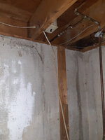
It looks like this wiring was originally code compliant, but at some point in
time it was altered.

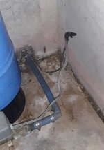
The splice connecting the well pump wiring to the pressure switch wiring
in hanging in the open. I think it would need a 2x4 attached to the wall,
then a junction box attached to the board, and place the splice inside.

It looks like the romex from the switch on the floor joist to the pressure switch
was at one time stapled to the vertical board, but was left hanging. I think
it just needs to be stapled to the board, but to do that it may need a longer
piece of romex.

Anything else?
 

Attachments

  • well-2.JPG
    well-2.JPG
    33.2 KB · Views: 9
  • well-1.JPG
    well-1.JPG
    40.7 KB · Views: 8
  • 20250902_100117.jpg
    20250902_100117.jpg
    486.7 KB · Views: 6
To avoid these ads, REGISTER NOW!

mike93lx

ALLIANCE MEMBER
Joined
Dec 9, 2013
Messages
37,591
Location
Richmond, VA
I'd mount a 4" square junction box over the wire entering the basement. Then use an appliance whip (sealtite) to connect to the pressure switch

The rocket switch should probably be mounted lower so it's actually accessible and all the romex needs protection from damage, so sleeving in conduit would be prudent.
 

75gmck25

Well-known member
Joined
Jul 21, 2014
Messages
1,325
Location
Alexandria, VA
The wire was probably stapled to the vertical board, which is usually considered sufficient protection for this type of installation (conduit is also an option). Then it could have a junction box near the bottom of the board, and a short flexible wire whip over to the pump. It should be an easy fix.

Have you located the GFCI for this circuit? it should be accessible for reset while standing on the floor, and I prefer them to be at about 4-6 feet so they are easy to see and reach.
 

mike93lx

ALLIANCE MEMBER
Joined
Dec 9, 2013
Messages
37,591
Location
Richmond, VA
The wire was probably stapled to the vertical board, which is usually considered sufficient protection for this type of installation (conduit is also an option). Then it could have a junction box near the bottom of the board, and a short flexible wire whip over to the pump. It should be an easy fix.

Have you located the GFCI for this circuit? it should be accessible for reset while standing on the floor, and I prefer them to be at about 4-6 feet so they are easy to see and reach.
My well was never on a gfci and on an old install, I wouldn't expect to see one
 
OP
B

bw77

Well-known member
Joined
Jul 10, 2009
Messages
1,322
Location
Upstate NY
Have you located the GFCI for this circuit? it should be accessible for reset while standing on the floor, and I prefer them to be at about 4-6 feet so they are easy to see and reach.
There is no GFCI on the circuit. It's 15 amp, 240V, hard-wired.
 

wyliesdiesels

Well-known member
Joined
Aug 14, 2012
Messages
20,022
Location
Modesto, CA
Is that black NM going out to the pump/well-head?

If so, NM is not permitted for use outdoors.

Where is the pump controller?
 
OP
B

bw77

Well-known member
Joined
Jul 10, 2009
Messages
1,322
Location
Upstate NY
Is that black NM going out to the pump/well-head?

If so, NM is not permitted for use outdoors.

Where is the pump controller?
My guess would be UF in a conduit. I don't see any markings on it.

The only pump controller (I am aware of) is the pressure switch.
I don't know what it looks like at the (dug) well. It's not a drilled well.
I don't know if the pump has been replaced.

House was built in 1974.
 

Attachments

  • uf.JPG
    uf.JPG
    52.8 KB · Views: 7
Last edited:
To avoid these ads, REGISTER NOW!

mike93lx

ALLIANCE MEMBER
Joined
Dec 9, 2013
Messages
37,591
Location
Richmond, VA
My guess would be UF in a conduit. I don't see any markings on it.

The only pump controller (I am aware of) is the pressure switch.
I don't know what it looks like at the (dug) well. It's not a drilled well.

House was built in 1974.
That conduit is likely only a sleeve through the foundation and it's just direct burial to the pump
 

larry4406

Well-known member
Joined
Jan 27, 2006
Messages
19,303
Location
Northern Virginia
My 2-wire 20A 240V direct wire well pump does not have a controller.

To make it real jack leg, steal power off the circuit upstream of the switch by grabbing L1 and ground for circuit 1 in the basement. Then grab L2 and ground for circuit 2 in the basement.

No don’t do this. Prior owner did and I tore it all out.
 

ptt49er

Well-known member
Joined
Jun 28, 2018
Messages
309
Location
Rock Hill, SC
I'm picking up a 60amp disconnect to use for just this case.

It gets old having to call the wife to trip the breaker on and off when I'm working on the well, the disconnect will let me clean up the wiring AND kill the power to the pump/switch when I'm in the well house!
 

PCustoms

Well-known member
Joined
Jul 23, 2011
Messages
23,030
Location
VT
My guess would be UF in a conduit. I don't see any markings on it.

I should take a pic of mine.

Black poly water line, black poly sleeve?/conduit? With 3 wire pump cable twisted up to a control box that is gutted and tied to NM-b hanging down to the pressure controller.

Absolute mess
 

wyliesdiesels

Well-known member
Joined
Aug 14, 2012
Messages
20,022
Location
Modesto, CA
My guess would be UF in a conduit. I don't see any markings on it.

The only pump controller (I am aware of) is the pressure switch.
I don't know what it looks like at the (dug) well. It's not a drilled well.
I don't know if the pump has been replaced.

House was built in 1974.
Ive never seen black UF but i guess theres a first for everything.

the only UF i see is the gray that is poorly spliced to whatever that black cable is.

Can you take a closer pic?
 
To avoid these ads, REGISTER NOW!
Top Bottom