To avoid these ads, REGISTER NOW!

Building a buggy: nobggrnchvy

Mr.N

Well-known member
Joined
Jul 13, 2005
Messages
2,222
Location
Mpls, MN
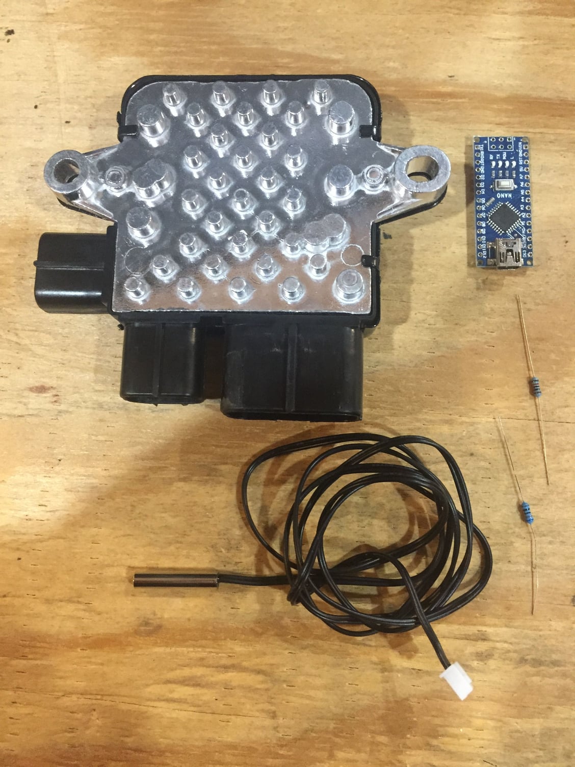
I also bought a used BMW 550i 850w brushless fan and a cheap PWM generator from ebay. I'm going to play with the signal and see if it operates the same way Spal brushless fans do. If it does, I just need a Spal thermostat and some connectors to have a fully modulating electric cooling fan. They're cheap too, less than $100.

20210818_174404.jpg
Very interested in learning more about this, would love any link or thoughts you have. Running just one?

I talked to a couple guys who use a couple switches to run the fan normal or backwards, saves them on hot days.
 
To avoid these ads, REGISTER NOW!
OP
B

bggrnchvy

Well-known member
Joined
Nov 14, 2011
Messages
589
Location
Pleasant Hill, CA
I talked to my foreman today about doing our skids like this, he kinda shot me down saying the owners wouldn't really go for it, especially since 75% our frames are made from pipe. Kinda ***** because we don't have any decent equipment in our shop. Everything is 30 years old and beat to hell so it really makes putting stuff together a nightmare and this would have made things so much easier.

Made from pipe seems like a better reason to do it than from square tube even. All the copes you have to keep track of and the angle without a flat surface for reference. A tube laser job shop would make it a lot easier on you guys if you have standard designs you build to.

Very interested in learning more about this, would love any link or thoughts you have. Running just one?

I talked to a couple guys who use a couple switches to run the fan normal or backwards, saves them on hot days.

There is a fan thread on Irate and couple of good ones on some LS swap forums I have found. I'll have to dig up the links. This fan is almost 19" in diameter it will take up the entire radiator by itself. If I can make it work, I might use some Volt 300w fans for PS and ****** coolers.

They're fully contained brushless fans unlike, older models, the controller is built in. Waterproof, dust proof, rated for 40k hours of service. All they need is a PWM signal for speed reference and +/- power. You can give them a straight signal from a switch to bypass if your PWM source goes south meaning they will run full speed when the switch is on. The only question is which brand fans run on which PWM signal, meaning is 100% full speed and 20% is slowest or is 95% slowest and 10% full? The Spal thermostats aren't adjustable, so if it's backwards your SOL. I bought a $15 PWM generator I will wire up to a battery and test the fan with soon. My friend uses the Spal thermostats to control the Spal brushless fans on his race car with great effect.

The big benefit for me is noise, I want this rig to be quiet. Not electric car quiet, but performance production car quiet in drivetrain noise. Having fans that only come on at low speed while crawling and just run enough to keep temps in check is ideal. I'm going to do my best to keep the engine noise down as well, I want it to be quiet at idle even if it's a little choppy.
 

Mr.N

Well-known member
Joined
Jul 13, 2005
Messages
2,222
Location
Mpls, MN
There is a fan thread on Irate and couple of good ones on some LS swap forums I have found. I'll have to dig up the links. This fan is almost 19" in diameter it will take up the entire radiator by itself. If I can make it work, I might use some Volt 300w fans for PS and ****** coolers.

The big benefit for me is noise, I want this rig to be quiet. Not electric car quiet, but performance production car quiet in drivetrain noise.


Same for the quite part. I've a pair of SS Flow master 50's and following them up with a couple cherry bombs to chase quite. My buddy this as he ran out of straight pipe, I got to ride in his jeep and thus...
 
Last edited:
OP
B

bggrnchvy

Well-known member
Joined
Nov 14, 2011
Messages
589
Location
Pleasant Hill, CA
I finished welding the engine crossmember out. It was clamped to the ****** crossmember while I welded out both sides and the exposed edges. When I flipped it to weld the inside seams I tried to fixture it to resist some of the shrink.

20210904_131200.jpg

I was unsuccessful. A fix was required as it drew in almost 5/16".

20210904_153602.jpg

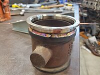
In between, my FIL had this inline exhaust brake that is designed for a C7 Cat in an MRAP. It is built as a direct mount off an elbow on the turbocharger. He is going to use it as an inline brake in his '02 Dodge Cummins. To make it bolt in he needed some V-band flanges welded on that he can weld the mating flanges into his exhaust. I had planned to bring it to work and spin it on a positioner but the amount of work to remove the blade and shaft to fully pull the cylinder bracket was quite a bit. Easier to just do little stiches.

20210905_130959.jpg
20210905_131811.jpg
20210905_132755.jpg

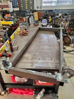
I decided it was time to put the buggy on wheels and make it mobile again. I chopped up the fixture rails and burned them together with some purchased caster plates and reused the casters from all the HF tool boxes to make a cart.

20210905_174255.jpg
20210905_175535.jpg

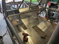
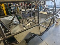
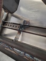
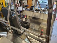
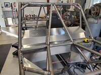
Back to work on the buggy itself, I started the tedium of panel fitment. So happy I went this route as all the panels I've dropped in so far fit great. A little touch with a 120grit wheel here or there, but no real surgery. Welding in all the tabs is a pain though. They're all premade in the same exact size and most fit up perfect but some miss by 1/8". As a result you have to build a nice little bridge of tacks upside down while you push the panel to get them to hold, in order to pull the panel back out and weld them out from the front. Fit is great though, so nice being able to bolt in an entire interior more or less.

20210906_162735.jpg
20210906_162421.jpg
20210906_163538.jpg
20210906_174120.jpg
 
OP
B

bggrnchvy

Well-known member
Joined
Nov 14, 2011
Messages
589
Location
Pleasant Hill, CA
I mounted some more sheet metal over the weekend. The rear sheet metal is now all tabbed in and I also got one one of the engine covers in.

20210912_172641.jpg
20210912_172602.jpg

I had to come up with a solution to preload the panel inwards to keep the gaps tight while I was running a foot pedal, torch and filler rod upside down. I ended up with a 1/4-20 bolt threaded into the backside of the unwelded tab pemnut with some paracord tied to it. I looped that around a tube on the far side of the chassis back to the nearside where I could draw it tight and tie it off. It worked pretty well.

20210912_132607.jpg

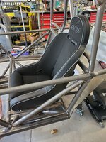
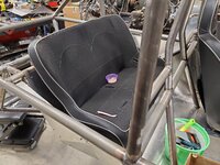
With the front seats home, I mocked one up to make sure the shoulder harness mount bars were correct. They were so those got installed and welded out as well.

20210912_173316.jpg

One other thing I did for my own piece of mind was sleeve the holes in the engine crossmember. The bolts are clamping on the narrow profile and the frame side mounts are a saddle as well but I've never liked or had good luck clamping through a hollow form. Especially when it's supporting something heavy.

20210911_125813.jpg

I opened the holes up to 5/8" and sleeved them back down to 1/2" (original hole size) for 3/8" hardware.

20210912_172749.jpg
 
OP
B

bggrnchvy

Well-known member
Joined
Nov 14, 2011
Messages
589
Location
Pleasant Hill, CA
I received a set of seat sliders that bolt into the vertical tab style mounts on these seats and deliver ~5" of movement.

20210919_130901.jpg

I mounted them onto one of the seats and set it in the rearward position and set the seat in the frame 1/2" from the B pillar. With that mocked up I measured out and came up with some tabs I lopped out of a drop of 1-1/2" .120w. I cleaned them up and put some offset 3/8" holes in them and bolted them in, tacked them, pulled seat and welded them out.

20210919_130934.jpg

They will need some support underneath, probably ribs under the center console/seat bracket and some stringers out to the rub rail from the narrow seat rails to offset the moment I've induced by mounting off center. I wanted to get the floor in first to see what I could fit though. A lot of work, but it will let me wife drive this as well being she is about 9" shorter than I am.

20210919_131235.jpg
20210919_131248.jpg

To fit the floor, I need to fit the entire firewall assembly as they all bolt together. To hang that I needed to weld in the passenger wiring bulkhead blank and the driver side orbital and brake MC mount.

20210919_150651.jpg
20210919_150708.jpg

Hard work done, almost without any adjustments bolted the entire firewall up. Amazed at how well it all fits, both panel to panel and panel nested in the frame. I had to use an aluminum burr in about 3 spots to clearance a couple of corners or tube reliefs, very minor.


20210919_165245.jpg
20210919_165331.jpg
20210919_172749.jpg
 
OP
B

bggrnchvy

Well-known member
Joined
Nov 14, 2011
Messages
589
Location
Pleasant Hill, CA
I cut up some more steel and made some tabs and return gussets for the seat mount tabs. I promptly cooked the welds on the tabs, less heat next time.

20210925_152252.jpg
20210925_134501.jpg

With the buggy upside down again, I burned in the extra pair of sway bar saddle mounts Goatbuilt sent out. I was missing the second pair in the kit originally.

20210925_155617.jpg

I righted the rig and pulled the floors and firewall to weld out the tabs I had tacked in place from below.

20210926_151211.jpg

Once all those were welded out and I put all the sheet metal and the driver seat back in for the time being, I fit the dash kit. Once again, it all dropped in, no fuss.

20210926_170006.jpg
20210926_170023.jpg
 

LXCam

ALLIANCE MEMBER
Joined
Apr 23, 2013
Messages
19,175
Location
AZ
Looking great BG!. But I've got a question.


With the seat mocked up, just how many times did you plop your **** in it and make vroom vroom sounds??.
 
OP
B

bggrnchvy

Well-known member
Joined
Nov 14, 2011
Messages
589
Location
Pleasant Hill, CA
Minor updates, we've been gone the last few weekends.

I burned together the front upper shock mounts after spending a bunch of time cleaning them of all the oil and most of the mill scale. They fit together nicely. They're for a 1.5" shock eye width so I put the 1.5" tube spacer in there and added .010" of shim and then bolted it together snuggly and tacked it all up before welding out the fillets and the tab and notches. They're tacked on to the nose of the buggy now, but I don't seem to have an image. You can kind of see them in the image below with the dash tabs.

20211002_155236.jpg
20211002_155228.jpg
20211003_130840.jpg

The rear seat arrived. My daughter affectionately refers to it as her couch and she sits in pretty regularly.

20211012_181202.jpg

I got all the tabs for the dash tacked in with the dash in place, then pulled everything I had to and welded them out.

20211016_144341.jpg

My wife started helping me tear down the front 60 so we can get tot he bare housing. I need to move it around and cut off all the factory bracket before welding on the truss, lower link mounts, ram mount and skid and it will be much lighter if it doesn't have all the guts in place.

20211016_122517.jpg

She got to this point and I realized the snap ring pliers I had we not going to cut it. I've since acquired some large Knipex pliers that should help remove the snap rings holding the unit bearings in place.

20211017_120733.jpg

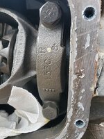
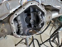
We pulled the cover to drain the oil, at the same time I stamped the caps for top and bottom orientation and driver and passenger side.

20211017_120725.jpg

Gears and carrier look great, shame they will be round filed. Nobody wants 3.55s.
 
OP
B

bggrnchvy

Well-known member
Joined
Nov 14, 2011
Messages
589
Location
Pleasant Hill, CA
Don't knock it, that is one reason the axle is so cheap...

It helped, but these are all so cheap it surprising.

My daughter was home sick yesterday, so in between watching her and keeping up with work by phone/laptop I stepped into the garage to try and make some little things happen.

I built the bump cans for the front and back. The kits Goatbuilt supplied are really well thought out in that they are self fixturing.

You get a tube laser cut can. It has the two small tangs left to keep the tube from collapsing inwards when you relieve the internal stress.

20211021_170540.jpg

In addition to the clamping bolts and the 4 total pieces of thick wall tube you get 4 washers and two snug fitting nut/bolts pre assembled. These press in, by hand, to the laser cut tube, nesting the thick wall tube pieces exactly where they need to be and maintaining all the geometry. Just tack, weld out, remove the bolts, trim the two tabs and insert the mounting hardware.


20211021_170603.jpg
20211021_181946.jpg

While I was at the bench I also welded out the skid plate for the steering ram since I had already cleaned and tacked it together last weekend. Need to work on the out of position work in regards to both consistency and stops/starts.

20211021_181954.jpg
 
OP
B

bggrnchvy

Well-known member
Joined
Nov 14, 2011
Messages
589
Location
Pleasant Hill, CA
I have had very little time to work on this project the last 3 weeks, but I was able to get a good chunk of time in this last weekend.

The project at hand is stripping the front axle down to the housing, then cleaning all the OEM brackets off which is a bear by itself, then cutting the cast housing down a couple of inches to revel more tube to weld to.

I stripped it all down, pulling the shafts/gears and all.

20211023_141529.jpg
20211023_135501.jpg

Then I started cutting, a 7in cutoff disc helps. I cut out the radius arm bushings to start and then started lopping off anything that stuck out.

20211113_164731.jpg

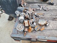
It took some time to both gouge out all the welds, and cut enough brackets out of the way to get to some of the welds. I put the sawzall to use chopping through large chunks of the casting. It ended up making quite the pile.

20211113_164737.jpg

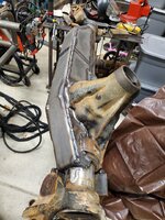
The last removal step was to cut the housing back 2" to leave more axle tube on the driver side. The truss that goes back on will makeup for any strength loss here. I marked out a ring with a tape and punch, then traced it with a sawzall and a 12" blade. Finally I used a 4-1/2" cutoff disc to make an insert cut and then a chisel and hammer to knock a piece free. Then I kept making shallow angled cuts to knock the rest of it fee leaving just the plug welds, which were ground down with hard wheel and flap disc.

20211114_115218.jpg
20211114_115902.jpg

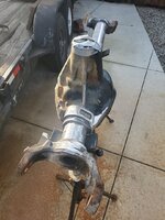
Another hour or so with a hard wheel contouring the housing, flap disc action to smooth it out and a little hot metal glue form the mig to fill any divots from aggressive cutting. Lastly, I used the tube sander to polish it all out and remove the OEM paint.

20211114_144747.jpg
20211114_144809.jpg

Next up, truss and ram mount, link mounts, sandblast the knuckles and weld on the steering arms. No more hours of mindless grinding.
 

Bodj Built

Well-known member
Joined
Feb 3, 2016
Messages
1,167
Location
Moorpark, CA
20211114_144809.jpg

Next up, truss and ram mount, link mounts, sandblast the knuckles and weld on the steering arms. No more hours of mindless grinding.

GREAT work! I hate removing old bracketry, which was a huge reason in why I went with a new 9" housings. Big kudos to you, that looks awesome.
 
OP
B

bggrnchvy

Well-known member
Joined
Nov 14, 2011
Messages
589
Location
Pleasant Hill, CA
GREAT work! I hate removing old bracketry, which was a huge reason in why I went with a new 9" housings. Big kudos to you, that looks awesome.
Thank you, definitely a labor intensive and dirty process. I would have loved to just buy fabbed 9" housings and run Gearworks 10" 3rds...but the money tree isn't that big.
 
OP
B

bggrnchvy

Well-known member
Joined
Nov 14, 2011
Messages
589
Location
Pleasant Hill, CA
Putting an off the shelf kit weld on arm always looks like an easy process. I had some challenges, some of which were self induced.

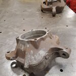
I started with a set of knuckles off an '08 Texas truck. I pulled the vacuum hose adapters and plugged them with 1/8npt plugs.

20211128_160209.jpg

Which I found out are the 09-12 lightened knuckles. Same mounting points of everything, but the casting is windowed in a couple spots and the contours are reduced.

I made the project longer by taking them to my BILs and sandblasting them.

IMG_20211206_062449_452.jpg

When I started fitting up the plates, the top plates had some major fitment problems with these later knuckles.

20211201_175249.jpg

The plates were trimmed back and I made up some add tabs to tie in to the second plane.

20211204_114257.jpg
IMG_20211206_062449_470.jpg

Beyond the top plates, the side plates needed some grinding and one just wouldn't work. I made a new one, but these come with a 1-3/8" hole on a 2" tall plate. Well, I only round hole maker I have at home 1-3/8" or less is 1", so one side ends up looking different. Not something you will ever notice when they're on the rig, but they look funny on the bench. Oh well.

I preheated them on the grill and turned the Dialarc up. All the horizontal plates got 2-4 passes top and bottom depending on joint. I installed a bolt in the rod end pocket with opposing nuts and prestretched it by about .035" big. It still shrunk up .015 short of 2" after I removed it when the assembly cooled. I guess I'll be turning the misalignment spacers down a little. The cast to mild steel joints were nickel rod and the mild to mild just ER70. I've seen a few arms welded with ER70 ripped from the casting (weld intact, just pulled out the casting). I was ok giving up a little tensile strength for the ductility and carbon mitigating effect, even if some say it is unnecessary with cast steel (not iron).

20211204_141258.jpg
IMG_20211206_062449_502.jpg
IMG_20211206_062449_528.jpg
20211205_144930.jpg
 
Last edited:

ed_

Well-known member
Joined
Nov 5, 2019
Messages
187
Location
Maine
Loving this build thread! Definitely going to be watching for updates
 

tarbellb

Well-known member
Joined
Apr 17, 2011
Messages
5,767
Location
Oregon
yeah, this build is so badass. thx for updating, cant wait to see the full package.
 
OP
B

bggrnchvy

Well-known member
Joined
Nov 14, 2011
Messages
589
Location
Pleasant Hill, CA
Loving this build thread! Definitely going to be watching for updates

yeah, this build is so badass. thx for updating, cant wait to see the full package.

Happy to entertain.

In other news, I got my black Friday East Coast Gear Supply order in. I now have no room in my office. Need to knuckle down and get the truss and ram mount on the front axle so I can pack it full of goodies and get onto the rear.

20211208_133730.jpg

Those of us who are used to 35 spline 4340 shafts and 1480 joints or remember the following and cost of a set of 35 spline 4340 Superior axles and CTMs joints for the old kingpin D60s will have a hard time digesting how cheap a 4340 40 spline set of front axle shafts is and how big the 1550 CTMs are.

20211209_134551.jpg

Not light either, something I had not put a lot of thought into is the increased rotating mass and unsprung weight. What's done is done though and at least I won't need spare front shafts. Hopefully I don't start eating the 10" 5.38s next.
 
To avoid these ads, REGISTER NOW!

Bigblue&Goldie

Well-known member
Joined
Mar 12, 2009
Messages
10,706
Location
AZ
I've been searching without luck for an overall length of the chassis (tip to tail); do you know what this is or can I bother you to measure it for me?
 
OP
B

bggrnchvy

Well-known member
Joined
Nov 14, 2011
Messages
589
Location
Pleasant Hill, CA
I've been searching without luck for an overall length of the chassis (tip to tail); do you know what this is or can I bother you to measure it for me?
14' and a couple inches.

In between life and holidays I've been picking away at the front axle truss. It's a Goatbuilt kit, but it is universal, so I had to do some work to fit it all.

The main structure and internal rib had to have the tube copes opened up to fit the 3-3/4" diameter axle tubes, luckily it comes pre-scribed for that and it's just a few minutes with the plasma and a flap disc to do.

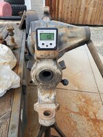
That done, I had figure out how much caster and pinion angle I needed to find where the truss would be plumb to. First order, find out the difference between pinion and caster on this axle.

Zero the caster:
20211211_120700.jpg

Measure the pinion angle:

20211211_120737.jpg

10.5 degree between them. Factor in the 3 degree offset bushings for the balljoint eliminators coming for the knuckles and aiming for 7* of caster I get 4* of caster from the mount with the truss at 0 and 6.5 degree of pinion inclination, which is good.

A peice of angle was clamped to the tube to set the angle, I found centerline and matched those as well, then I found the truss interfered with the pumpkin at the deepest point by 5/8". So I sat the truss on two 5/8 bolts to get it to site level.
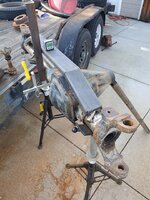
20211211_130434.jpg

To get the contour to cut, I grabbed a compass and set it to 5/8 and just traced the outline of the pumpkin onto any truss it contacted. A little time with the plasma again and a grinder and we had clearance.

20211211_150604.jpg

The backbone of the truss was welded in the corners to secure its shape, then I welded the points of contact with the tubes, as it's all rolled steel and ER70 and a few hundred amps works fine. Before moving on I bolted the Ruffstuff cover on to try and add some more stability to the housing.

The trickier was then welding the housing to the truss. This is nodular iron and I can't fit it in bbq. I spent a while trying to warm it up with a Mapp gas torch, then cranked the welder up to 250a and laid a bead on the casting only of ni99 filler. This gave me a wide throat tying into the cast and made sure everything was very hot. With the initial pass done, I made a root pass, with ni99, joining the two peices at the same settings moving quickly to not blow through the 3/16" truss. Finally I laid a cover with more ni99, washing all 3 passes together followed by post heating. No cracks.
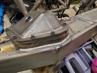
20211212_173945.jpg

Somewhere amongst all that I trimmed the plates to fit the housing and tacked them all on, and in some places welded them to the pumpkin.

20211219_161829.jpg

With everything tacked, I stitched the truss together to hold the shape and keep the tacks from breaking while I welded it out.

20211226_155509.jpg

Welding process was a few inches at a time front and back, alternating as much as possible to bring it all up to temp. When I finally got the root done on it all, the plate to axle tube got an almost continuous cover pass, just er70, to increase the throat.

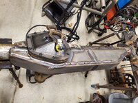
20211227_165722.jpg
20211227_165733.jpg20211227_165743.jpg
20211227_212231.jpg

Ram mount is next up and I've already done the rough fit. Should have an update in a few days.
 
OP
B

bggrnchvy

Well-known member
Joined
Nov 14, 2011
Messages
589
Location
Pleasant Hill, CA
A few more hours in this weekend. I really wanted to have the ram mounted before I ran out of time Sunday and we got there, with some room to spare.

Per directions, I cleaned the nuts that will act as threads for the ram skid and welded them in place. I did not have a flat head cap screw to center them, so I made one without resorting to the lathe with a drill and flap disc. I might need to make a set of these to have around in common sizes.

20211231_143900.jpg

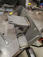
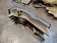
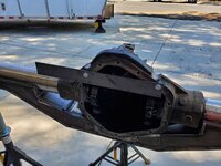
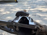
Mount was trimmed and notched to fit the axle, moved over enough that I could get the 3 offset clamps for the ram on where I wanted but still pull the carrier. Then it got welded out, ni99 on the housing like the rest, all of it got a second pass. There is an internal plate that tab indexes (you can see the tab welds) that was welded out internally. After installing the plate I was able to reach in from the side with the mig and get 2-3" of weld to the front truss plate.
20220101_142742.jpg
20220101_144932.jpg

One cover bolt was not easily accessible, a few minutes with a carbide burr got clearance for a socket to take it in and out.

20220101_144937.jpg

With the mount hanging over the cover, there's a combination of a no second plane at the top and a big moment on the bottom I just felt like I could fix. So I added a little tab up top to wrap the corner and box in the bracket and did a similar thing on the bottom but with two, so it unbolts with the cover. The hole has enough clearance for a cover gasket and I did have to trim the ram skid a little. Probably overkill, but it gives me some piece of mind. Current bolt will be swapped for a hardened one when I can pick one up.

20220102_125025.jpg
20220102_125306.jpg

Finally it was time to mockup the ram. I got it centered and then adjusted height to to be very close to the steering arms on the knuckles, which I can't mount yet because the ball joint eliminators are still 'shipped' without only the label created a month later. With everything lined out, I welded out the mounting feet.

20220102_133551.jpg

With the ram all but mounted I decided to sneak in the upper link mounts as well. I cleaned them up, prepped the weld area and bolted it all together with the spacers Goatbuilt supplies and clamped it to the truss right on the scribed lines, very easy. It all got tacked a dozen ways and then welded out.

20220102_145656.jpg
20220102_202337.jpg

So that's were it sits.

20220102_161642.jpg

Thinking about adding some mechanical stops for the ram end caps, unsure as 3 clamps is probably enough, but I would hate to loose it.

Next step is lower link mounts, with integrated coilover mounts. With the short side tube being quite so short, and the 3.75" diameter, they need some love (probably from the plasma) and I just wasn't up to the task end of day Sunday. Soon.
 
OP
B

bggrnchvy

Well-known member
Joined
Nov 14, 2011
Messages
589
Location
Pleasant Hill, CA
Small updates really.

I built captures for the ram to supplement the clamping force in keeping the ram in position. The captures are from drops of 1/8" Domex 100, I was able to form the driver side bracket, the passenger side was made in 3 pieces. There is relief for the clevises on the end of the ram shaft to clear, though I don't think I will get the full 10" of throw when done so it might not be needed. They took a bit of work, both in building/fitting and in welding out to get the fit perfect. As is, you have to get the ram almost perfectly parallel and then drop it in and you seat it with body weight.

20220109_135700.jpg
20220109_141602.jpg

I fit and welded out the lower link mounts, welded on the tear drop weld washers to the coil over mounts but only tacked those on. I need to move the front axle forward a few inches for drivetrain length reasons so they may need to get angled back a little more. The lower links ideally would have been a little narrower, but with the cast SD60 housing I am stuck at this width. Waffling on straight 7075 or 4130 HT'ed lower links or maybe going bent 4130 HT'ed lowers with a wobble stopper of some fashion to get the full 10" of ram stroke in steering.

20220116_122103.jpg

Then I moved the axle off the stands (yay crane) so I could move to the next project. I'm actually surprised it's only 220lbs (244 minus the ram) actually.

20220116_123014.jpg

The rear 14 bolt started here, intact and very heavy.

20220116_132958.jpg

I pulled the brakes, axle shafts, hubs and carrier out to lighten it so I could move it around. Carrier (G80) was junked, I found a piece of the governor gear on the magnet, so I'm sure it was already broken. It's getting a spool in any case.

The axle got moved it onto the stands after I tossed the cover back on.

20220116_151958.jpg

And I started cutting and beating. Bump pads, brake line tabs and shock mounts came off before I was done. Perches are next.

20220116_170513.jpg
 
OP
B

bggrnchvy

Well-known member
Joined
Nov 14, 2011
Messages
589
Location
Pleasant Hill, CA
14 bolt cleaned up and in the operating room.

20220123_155359.jpg

I tacked the rear truss together after cleaning it all up.

20220203_154916.jpg

To mark out the trim of the universal truss I made a fixture of sorts out using a couple pieces of angle, some spacers for the truss and a 2x4 to lock in the pinion angle.

20220203_164425.jpg
20220203_164429.jpg
20220205_161138.jpg

Truss fit to the housing, I welded in the missing pieces and added a couple shims so the bump areas would fit tight to the tubes.

20220206_140703.jpg

Then I worked my way back and forth, front and back tacking, then stiching methodically the truss to the housing. I made a filler piece to join the back of the truss to the housing as the relief as cut from GB didn't leave a lot left on one side. It got burned together with the ni99 rods leftover to the housing and er70 to the truss. Same on the front, minus the extra plate.

20220226_140843.jpg

Tube to truss mates got a cover pass.

20220227_132215.jpg

Truss welded out I started laying out the TMR shave kit. With the starting point I'm just going to shoot it with the laser to transfer it around.

20220227_133301.jpg

Of course the laser is at work, so I changed gears. The balljoint eliminators had come in so I toasted the knuckle again and welded in the uniball cups, followed by trimming the split bushing to establish adjustment and bolting it all together.

20220227_151816.jpg
20220227_173312.jpg
20220227_174230.jpg
 
OP
B

bggrnchvy

Well-known member
Joined
Nov 14, 2011
Messages
589
Location
Pleasant Hill, CA
Finished up the housing side of the axle shave. I still need to chuck up the ring gear and turn it down a half inch.

To where we left off, I used a laser to transfer my cut line across the ribbed housing.

20220305_144901.jpg

Prior to digging in I added a support to try and keep the housing from springing open after I pulled the lower lip since I welded the truss on the backside. Likely futile, but a couple of 5/16 holes took 2 minutes to do.


20220312_121912.jpg


A 7" grinder got most of the way through, but I had to finish it with the sawzall and a 12" blade.

20220312_124552.jpg


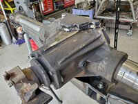
I welded it in and out, again with the Ni99. After building up the outside bead with 4-5 passes, I tried to wash it a bit more uniform and it looks like giant cold mig tacks :confused: That's what I get for not leaving well enough alone. Oh well.
20220312_152721.jpg
20220312_155202.jpg

Axle housing done, I needed to lop the bottom off the Ruffstuff cover to match the TMR shave kit. I leveled the housing, then bolted on the new piece for the cover and rotated the axle so that piece was level. It has a 6° difference to the bottom plate. Then, back out came the laser and I adjusted it's height to the bottom of the plate to be welded in, which was in the same plane.

20220313_133714.jpg
20220313_133753.jpg

Then I removed the plate to be welded in and bolted on the cover without moving the laser to get my cut line. Worked out quite well. I did take the cover off to cut the lip off after I traced the laser line.

20220313_134147.jpg
20220313_140622.jpg
20220313_142006.jpg

I tacked the snot out of it and then did a root and a pair of cover passes with ER70. I also pulled it off and welded out the inside.

20220313_144746.jpg

For the last item since I just plated the bottom of the housing in mild rolled steel, I stole a few sticks of Stoody 31 hard facing rod from my BIL (he's a foundation driller, so he hard faces all the time) and put a pattern on the bottom. The last time SMAW'ed anything I hadn't graduated HS, so it is as good as I could hoped for. The hard face should be about RC47, about as hard as a low quality knife.

20220313_172735.jpg

Finished for now. Onto the 205 next.

20220313_173600.jpg
 

zmotorsports

ALLIANCE MEMBER
Joined
Oct 20, 2009
Messages
21,441
Location
Northern Utah
Nice work on the axle shave. Can I ask what you are using for a laser level? Do you like it? Anything you would do differently or another one you would buy if not this one? I have a cheap old turd of a thing and keep flirting with upgrading.

Thanks.
 
OP
B

bggrnchvy

Well-known member
Joined
Nov 14, 2011
Messages
589
Location
Pleasant Hill, CA
Nice work on the axle shave. Can I ask what you are using for a laser level? Do you like it? Anything you would do differently or another one you would buy if not this one? I have a cheap old turd of a thing and keep flirting with upgrading.

Thanks.
I have a couple, and have access to a 3rd.

The first one that is at work is a Bosch cheapy:


It works well enough, but the red laser is hard to see in a lot situations. Good in a room, not quite so good in a shop with any big doors open.


I actually bought this green one specifically for this project, remembering the visibility issues of the red laser. It's even cheaper than that cheap Bosch unit. It's a bit touchy about leveling out, since it's just a gimbal, but locks up solid when you slide the lock switch. For the price, it is hard to beat.

My BIL has a grading laser for his business I've used a half dozen times and it's amazing to shoot grade and slope elevations. I literally couldn't have gotten by without it as a single individual. That said, it's not cheap.

 
To avoid these ads, REGISTER NOW!
Top Bottom