To avoid these ads, REGISTER NOW!

Building a DIY CNC Plasma Table....

Jehannum

Well-known member
Joined
May 3, 2012
Messages
1,350
Location
Albuquerque, NM
More parts have been arriving by the day.
Z axis motor, or Torch Height Control. 0456F5D2-A9E2-4DE7-8529-2A6DDB2464E4.jpeg

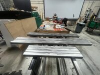
Also the linear bearings and rods arrived…

Printing is ongoing, and the Ender has been basically running 24/7 for 2 weeks now. Lol.
I’ve had a couple of parts fail for a few reasons, but it’s going good.
By my calculation I have 6 or so more prints to do, all smaller parts.
Because I’m going with a bridge Y axis, I’ve got double the gantry flanges and bearing blocks to print. They take between 30 and 44 hours a piece to print.
The filament I’m using seems to be good, and with 80% infill they seem substantial.
I think I’m going to be close to 4kg or 4x spools when I’m done.

Parts printed so far.
6BC8F8B1-FABA-44D4-B648-576F9D99CC31.jpeg

As the Ender has been fully committed to this project…
Decided to add another printer to my collection.
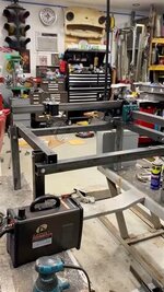
Everything for this CNC Plasma Table has been printed on my Ender 3 v2. Only has a 220x220x300 envelope but everything fits. .
The new printer is a Longer LK5 Pro that has a 300x300x400 envelope… I need to for some other stuff I’m planning.

D42D3EE0-E626-434F-B90C-D5F26EB6B91B.jpeg

I will be starting to process the printed parts this weekend, and next week I’m planning to get down to the metal store and get my Tubing.
I was in a similar position, but ended up getting a CR-10, because the Creality backplate let me replicate all the changes I made to my Ender 3 (direct drive, bed leveling probe, e3d v6 hot end, TH3D 32-bit mainboard) without having to find/make new mounts.

The only thing that I didn't like out of the box on the CR-10 was no dual Z-axis. I fixed that fairly quickly though.
 
To avoid these ads, REGISTER NOW!
OP
K

Keyblazer

Well-known member
Joined
Jul 30, 2009
Messages
1,471
Location
Irvine, CA
My main job(Employee Benefits) got busy as so many people renewing for December and January, so not got as much done as I’d hoped…

However, parts have still been arriving!
This is nearly everything on the electronics side now.
450w 24v Power supply.
2x Nema 23, 425 oz/inch torque stepper motors for the Y axis as I’m going bridge style.
2x Dm556 controllers for above.
1x Nema 23, 269 ox/inch stepper motor for X axis.
1x TB660 Controller for above.
Arduino.
959A244D-E330-4BBD-9AB7-9364C95F4838.jpeg

Started assembling the Z axis(THC).
Have yet to get the hardware, and holes to drill and tap.
68FA7C46-75DC-4F5E-9270-5DF1C32DA250.jpeg

Did some trial Cable Chains… not 100% happy with them, so will wait to print more.
4D53BB3F-3EE2-4222-A9B8-8C748F04E075.jpeg

I did decide on my frame size!
Current plan is that the Cutting envelope will be X48”x Y36”
Planning to go to the metal store today, and see if they have what I need…
 
OP
K

Keyblazer

Well-known member
Joined
Jul 30, 2009
Messages
1,471
Location
Irvine, CA
Oops, missed your question, Mike!
Yes, I plan to run a water tray, which I plan to fab myself.
My run to Industrial Metal Supply, here in Irvine, Ca, was a part success. I found about a third of the total length of 2”x 0.065 wall square tube I need for the frame in the Drops/Rems section. The $0.99c/lb is a good price.
Bought 5x more 2.5” 0.125 wall square tube than I need for this plasma table… but it was cheap, and won’t go to waste.
Also found a good slab of 6” plate that is needed for the the Y axis joint plates, but it was 5/16 thick rather than the 1/4” specced in the plans, so I will see if that will work.
Spent $110 there, but I’m thinking only $50 ish of it goes toward the Plasma table.

Maybe I need to go back, edit in a running cost total if people want?

I think I have enough to play with for now, and hopefully they have more 2” square next time I go, in the new year.

45CB9FCA-91C5-4D9A-BE48-3F693B69E7A5.jpeg
 

fordkid88

Well-known member
Joined
Nov 10, 2013
Messages
680
Merry Effin Christmas to you all!

More “Control” stuff arrived.
Z axis driver.
Pulleys
Belts
Bearings.
Torch relays
Shielded usb cable(Already had).

F26C936F-89A8-4620-8889-3070826F1366.jpeg
I'm looking forward to this, I've got the same relays for mine. I'm in the wiring process and testing a new gantry design. If all goes well this weekend I will be up and moving soon.
 
OP
K

Keyblazer

Well-known member
Joined
Jul 30, 2009
Messages
1,471
Location
Irvine, CA
Awesome!
I think the thread title is broad enough to cover ALL DIY builds, so please share!
We are all in this boat together, and can learn something!

Is there a DIY CNC Router thread somewhere on GJ?
I'm thinking if im going to get into CNC, I need one!
Looking at Print NC and MP CNC... very interesting...
 

Meleon

Active member
Joined
May 25, 2013
Messages
32
I just ordered the steppers, drivers, belts and all the other misc. bits last night. the 2x2 x .06thk tube is pretty spendy here in Canada. $275 for 20 feet. (and that at cost from where I work)
eager to started on this one.
 

fordkid88

Well-known member
Joined
Nov 10, 2013
Messages
680
PXL-20230103-221757149.jpg
PXL-20230103-222246250-MP.jpg
Here's what I have so far, don't mind the mess it's small room with a lot of tools crammed in it. I'm working on the control cabinet right now. I have a little welding left and to form the cable trays at work and then it's a bunch of little hardware left to order.
 
OP
K

Keyblazer

Well-known member
Joined
Jul 30, 2009
Messages
1,471
Location
Irvine, CA
Nice!
A lot beefier than the one I'm building!

As promised, here is a Breakdown of my costs so far:

1/
3x 1 KG Rolls filament. SUNLU 3D Printer Filament, PLA Meta Filament 1.75mm, Toughness, 1 KG Spool, Grey.
Amazon. 3x $14.44 = $43.32

2/
Y Axis. 2x Nema 23 Stepper Motor 4.2A 3.0Nm (425oz.in) 100mm Length with 8mm Shaft for CNC Mill Lathe Router. Amazon.
Amazon. 2x @$36 = $72.00

3/
Y Axis: CNC Digital Stepper Driver DM556 Stepper Motor Controller 2-phase Stepper Motor Driver 20-50V DC Max 5.6A 128 subdivision For Nema 23, 24 and Nema 34 stepper motor.
Amazon 2x @ $22.99 = $44.98

4/
X Axis: 1x Nema 23 Stepper Motor 2.8A 1.9Nm (269oz.in) 76mm Length with 8mm Shaft for CNC Mill Lathe Router.
Amazon. 1x @ $26.00

5/
X Axis: CNC Digital Stepper Driver DM556 Stepper Motor Controller 2-phase Stepper Motor Driver 20-50V DC Max 5.6A 128 subdivision For Nema 23, 24 and Nema 34 stepper motor.
Amazon. 1x @ $9.98

6/
WINSINN GT2 Pulley 20 Teeth 8mm bore 10mm Width 20T Timing Belt Pulley Wheel Aluminum for 3D Printer (Pack of 5Pcs).
Amazon $7.99

7/
Arduino UNO REV3 [A000066]
Amazon. 1x @ $ 28.50

8/
InShareplus 24V 18.75A 450W Universal Regulated Switching Power Supply, 100-240V AC to DC 24 Volt LED Driver, Converter, Transformer.
Amazon. 1x @ $30.99

10/
Torch trigger relay: HiLetgo 2pcs 5V One Channel Relay Module Relay Switch with OPTO Isolation High Low Level Trigger.
Amazon @ $7.39

11/
3D Print Open GT2 Timing Belt 5 Meters (16.4 Ft) Length 2mm Pitch 10mm Width with 3D Timing Belt Pulley and Idler.
Amazon. 1x @ $11.99

12/
10 Pack R4ZZ Double Metal Seal Bearing 1/4 x 5/8 x 10/51 inch, Pre Lubricated,Stable Performance,Cost Effective, Deep Groove Ball Bearings
Amazon. 1x @ $8.20


So, this list comes to:
$291.34

More to come!
 

fordkid88

Well-known member
Joined
Nov 10, 2013
Messages
680
PXL-20230110-032515616.jpg I don't know how wiring you have with the setup you're going for but these little connectors I got off of Amazon are pretty slick and they're cheap. You lift the levers slide your wire in and close the lever.
 
OP
K

Keyblazer

Well-known member
Joined
Jul 30, 2009
Messages
1,471
Location
Irvine, CA
Cool.
Thanks for the input.
Was hoping to cut some steel tube this last week, but it’s been raining non stop.
 
Last edited:

midwestracer2003@yaho

Active member
Joined
Jun 7, 2022
Messages
40
so my original plan being I don't have a 3d printer was just to but the parts from them but after some thought what do you recommend for a 3d printer seems this would be the best course of action but a whole other hole to dive into so many choices
 

tiggen

Member
Joined
Jun 27, 2011
Messages
18
Also interested in this build as I have bought the plans. I built a BOM with prices, which is currently at $675. That's for XY and Z axes, 3d parts from JD's garage, the water table pan, all new hardware for assembly, and steel tube of frame. It does not inlcude one of the motors (currently out of stock on Amazon, but only $20-30) nor does it include the fair amount of other steel (plate, bar and angle) needed. Don't currently have the budget for a plug and play, and I don't currently have the time to fettle a machine that may need lots of fettling.
 

midwestracer2003@yaho

Active member
Joined
Jun 7, 2022
Messages
40
Bought a ender 3max and it just came in also ended up buying a crossfire used with cutter for 800 so will use that to start but still going to build one of these but bigger 2x4 ot 3x4 instead of expanding the crossfire
 
To avoid these ads, REGISTER NOW!

stillnostrebor

Well-known member
Joined
Apr 1, 2019
Messages
619
Location
SW Missouri
Also interested in this build as I have bought the plans. I built a BOM with prices, which is currently at $675. That's for XY and Z axes, 3d parts from JD's garage, the water table pan, all new hardware for assembly, and steel tube of frame. It does not inlcude one of the motors (currently out of stock on Amazon, but only $20-30) nor does it include the fair amount of other steel (plate, bar and angle) needed. Don't currently have the budget for a plug and play, and I don't currently have the time to fettle a machine that may need lots of fettling.
I'm at $1,100 with a plasma cutter for this setup.

I don't really have time for it either, but I want to get into this world, and believe it is better to build this so I understand the machine more deeply. At some point shortly after completion it will pay for itself, so the dollars were not my primary motivator.
 

Jammer0369

Member
Joined
Mar 5, 2013
Messages
11
Location
Arizona
Any updates? I just bought the plans this week. I already have all of the 2" steel needed for the frame. Planning on going ahead with the Z-axis from the start.
 

stillnostrebor

Well-known member
Joined
Apr 1, 2019
Messages
619
Location
SW Missouri
Plasma Table 1.jpg
I am this far along on mine...

The printed tube spacers are a bit fragile. I'm going to do something different there. Otherwise the thing is going together as planned. I matched the height of mine to my other rolling benches, so I need to add some lower cross bars.

Still chipping away...
 

tiggen

Member
Joined
Jun 27, 2011
Messages
18
Fyi, I have decided not to go forward on this. As bad as I want a plasma table, I simply don't have the time or money right now. Still watching with interest. Hope it continues to go well!
 
OP
K

Keyblazer

Well-known member
Joined
Jul 30, 2009
Messages
1,471
Location
Irvine, CA
I've made no progress with mine... as per my Garage thread, there have been too many distractions.
 

guyg123

New member
Joined
Sep 9, 2023
Messages
1
Hello all. I've just started out on mine, glad I found this thread although feeling slightly less confident about how much it is to take on...here's the first parts including biggest fail so far.

I chose PETG for toughness and longevity but I have not found printing it on the Ender 3 easy. I could only print the Belt Mounts on a raft and the spacers with a brim. Just tried printing the Gantry Flange on a raft and it sank, peeled up at one corner. Direct to bed next (me and the print I think).

I would like a larger capacity - thinking about the bearing method to extend the X axis, and I guess Y is limited by belt stretch, but no idea really.

Anyway, thanks for posting everything and hope you get back on the horse soon.
 

Attachments

  • IMG_20230909_210726.jpg
    IMG_20230909_210726.jpg
    726 KB · Views: 107

christopizza

Well-known member
Joined
Dec 3, 2010
Messages
129
Location
NC
The first spacers I printed were a bit fragile. I switched to PETG and they improved but were harder to drill out to 3/8.

I'm isolating the control box from the frame and grounding the cable shields within the control box. I am not connecting shields to the motors. I'm a pretty good scrounger and was able to find a good bit of the metal I needed stashed out back.

Stripping old paint was a Pita and I removed mill scale outside with some acid I have for that purpose. After that was a light sanding on all parts and a more second sanding on the steel parts that will contact bearings.

Between Tractor supply and my various leftovers, I had enough hardware to assemble. The bearings were not hard to assemble to the blocks and after a bit of adjustment, slide freely without play on the 2x2 steel.

Control box is assembled and all motors tested with the Openbuilds software and gbrl on the arduino. It was really easy or I was lucky.

Cheers!
 

Attachments

  • frame small.jpg
    frame small.jpg
    1,012.9 KB · Views: 79
  • axis test.jpg
    axis test.jpg
    96.6 KB · Views: 73
Last edited:

christopizza

Well-known member
Joined
Dec 3, 2010
Messages
129
Location
NC
First trial went well. My torch wasn't firing off, but I had a faulty relay. Spare works a treat.

Link to youtube as the video is too much for the forum.


Now to figure out how to setup Fusion 360 to work with the torch and make some more test cuts!

I 3d printed a dimple die for the bar sink drain I'm fitting to the tray. My first attempt worked but was a bit small -- I'm printing @ 5% larger and stretching the z a bit on my next trial. https://www.thingiverse.com/thing:5498416

My intention is not to steal this thread but to provide incentive to finish the ones that have been started. Thanks!
 

CreateStage

Member
Joined
Mar 28, 2022
Messages
18
Hey guys! I love this! I am about to assemble my JD's Garage. I am building a 48" x 48" cutting area so 58 1/2" x 67 1/2"so I had to get creative with the sizing. It is a bit out of the suggested comfort zone but I figured I would build it and upgrade some parts if the build is not suitable for precision. The crazy thing is, I can not get the templates to size accurately! The 4 x 4" square for the printer calibration is coming in under a 32nd on the X and over a 64th on the Y. Has anyone had problems with the templates? It is way under at 100% and at 103% I am getting the measurements mentioned earlier. This is maddening! I have everything ready to go and I can't get the templates to print right. FYI, JD's Garage (emailing them) was way less than helpful!

Yes, I understand they suggest the maximum reliability of the belt system is maxed out at 5' and I am technically 7 1/2" over that with my build. I am building a bridge for the gantry so each side with hold the gantry.

I am excited to share this build with everyone but I just can't crack this stupid printer error! I figured just setting the printer settings at 100% would be all good. That is the first two pictures. In the second two, the printer is set at 103%. I don't think I can set it to 103.25% (that's a joke) but regardless, for me and my stupid printer anyway (very typical, Brother HL - L23900W printer) the drawing is NOT SQUARE!

Any suggestions are welcome! Thank you in advance!
 

Attachments

  • JD's Garage Build_3.jpg
    JD's Garage Build_3.jpg
    306.4 KB · Views: 53
  • JD's Garage Build_2.jpg
    JD's Garage Build_2.jpg
    259.3 KB · Views: 37
  • JD's Garage Build_1.jpg
    JD's Garage Build_1.jpg
    318.9 KB · Views: 32
  • 103_Y.jpg
    103_Y.jpg
    356.1 KB · Views: 34
  • 103_X.jpg
    103_X.jpg
    484.1 KB · Views: 32
  • 100_Y.jpg
    100_Y.jpg
    351.4 KB · Views: 32
  • 100_X.jpg
    100_X.jpg
    347.5 KB · Views: 50

CreateStage

Member
Joined
Mar 28, 2022
Messages
18
Hey guys! I love this! I am about to assemble my JD's Garage. I am building a 48" x 48" cutting area so 58 1/2" x 67 1/2"so I had to get creative with the sizing. It is a bit out of the suggested comfort zone but I figured I would build it and upgrade some parts if the build is not suitable for precision. The crazy thing is, I can not get the templates to size accurately! The 4 x 4" square for the printer calibration is coming in under a 32nd on the X and over a 64th on the Y. Has anyone had problems with the templates? It is way under at 100% and at 103% I am getting the measurements mentioned earlier. This is maddening! I have everything ready to go and I can't get the templates to print right. FYI, JD's Garage (emailing them) was way less than helpful!

Yes, I understand they suggest the maximum reliability of the belt system is maxed out at 5' and I am technically 7 1/2" over that with my build. I am building a bridge for the gantry so each side with hold the gantry.

I am excited to share this build with everyone but I just can't crack this stupid printer error! I figured just setting the printer settings at 100% would be all good. That is the first two pictures. In the second two, the printer is set at 103%. I don't think I can set it to 103.25% (that's a joke) but regardless, for me and my stupid printer anyway (very typical, Brother HL - L23900W printer) the drawing is NOT SQUARE!

Any suggestions are welcome! Thank you in advance!
Ok, I just updated the drivers and printed from USB vs WIFI. Printed perfectly when put to actual size
 

fordkid88

Well-known member
Joined
Nov 10, 2013
Messages
680
Can we hi jack this thread keyblazer and turn it into a DIY plasma table thread with build links and tips.
 

stillnostrebor

Well-known member
Joined
Apr 1, 2019
Messages
619
Location
SW Missouri
Assembler's note:

When you are trying to get the bearing, along with the two plastic washer/shims, to line up with the 5/16" rods in the narrow slots for the bearing block assembly and you get so mad that you create new golfing words... I have a solution that helps quite a bit. I put a dab of Assembly Goo on each side of the bearing and stuck the tiny plastic washers to the bearing before placing the whole assembly into the printed part. It still took some poking to get the bearing and both washers into the slot, but the Assembly Goo holds the washers in place so you can feed the steel shaft through. It just takes a tiny bit on the inner bearing race edge. This worked 100x better than trying to get the washers to line up freestyle.


This is what you use to assemble fussy small parts together and hold them in place in an automatic transmission. It wont harm anything and made an infuriating job just slightly frustrating.
 

stillnostrebor

Well-known member
Joined
Apr 1, 2019
Messages
619
Location
SW Missouri
Also of note, I purchased a chunk of 5/16" OD CRS rod to make the pins for the bearing blocks, and my material measured out a bit over 5/16", but within a reasonable tolerance for that dimension. The bearings are 8mm, which is just a fuzz over .3125, so my smooth rod didn't fit. 8mm is really what you want if you purchase a pre-made material.

I turned mine down to fit. You can also use 5/16" bolts that are long enough to cut the threads and head off, leaving the unthreaded part of the bolt, from what I have read.
 

fordkid88

Well-known member
Joined
Nov 10, 2013
Messages
680
Also of note, I purchased a chunk of 5/16" OD CRS rod to make the pins for the bearing blocks, and my material measured out a bit over 5/16", but within a reasonable tolerance for that dimension. The bearings are 8mm, which is just a fuzz over .3125, so my smooth rod didn't fit. 8mm is really what you want if you purchase a pre-made material.

I turned mine down to fit. You can also use 5/16" bolts that are long enough to cut the threads and head off, leaving the unthreaded part of the bolt, from what I have read.
Could you put the rod in the freezer and shrink that .002, maybe warm the bearing up as well?
 

stillnostrebor

Well-known member
Joined
Apr 1, 2019
Messages
619
Location
SW Missouri
Could you put the rod in the freezer and shrink that .002, maybe warm the bearing up as well?
As fussy as these are to put together, I don't think that would work. It takes quite a bit of time to assemble one bearing set. The shaft really needs a bit of clearance to aid in getting this all assembled.
 

stillnostrebor

Well-known member
Joined
Apr 1, 2019
Messages
619
Location
SW Missouri
20240114_212417.jpg

Some progress...

I steel sleeved the spacers at the tube joints, added a platform at the bottom for stability, and completed the gantry assembly this weekend. The platform at the bottom is built from old bed frame tube, so my recycled shop equipment status can be maintained.:)

Another weekend of farting around should have me well into the electronics.
 

fordkid88

Well-known member
Joined
Nov 10, 2013
Messages
680
20240114_212417.jpg

Some progress...

I steel sleeved the spacers at the tube joints, added a platform at the bottom for stability, and completed the gantry assembly this weekend. The platform at the bottom is built from old bed frame tube, so my recycled shop equipment status can be maintained.:)

Another weekend of farting around should have me well into the electronics.
I like the progress, I'm hoping to get the last of my material ordered and cut in the next 2 weeks so I can get it off saw horses.

Is that water tray stainless? I was thinking of doing a stainless tray myself as I work in a stainless fab shop, but I'm too cheap to do one the size and material gauge I need.
 

stillnostrebor

Well-known member
Joined
Apr 1, 2019
Messages
619
Location
SW Missouri
I like the progress, I'm hoping to get the last of my material ordered and cut in the next 2 weeks so I can get it off saw horses.

Is that water tray stainless? I was thinking of doing a stainless tray myself as I work in a stainless fab shop, but I'm too cheap to do one the size and material gauge I need.
It is stainless. This is the tray JD Garage suggests in the bom.


gpiggaz

Well-known member
Joined
Mar 14, 2010
Messages
2,548
Location
Tucson, AZ & Edmonds, WA
I'm 3/4 of the way finished with my JD's garage build, Still haven't ordered the Plasma cutter, leaning towards getting the Primeweld Cut 60. Can't justify the Hypertherm units since this is just a "toy" for me. The other cheaper plasma cutters don't seem as nice as the Cut 60 - I'll probably spring for the machine torch, it's "only" another $300:)

I'm quite a bit over budget for the build, I've connectorized the electronics - put it in a nice box That added almost $200 to the build costs. I made it a little taller than the plans call for, and added casters so it's mobile. Plus I bought all new steel which is more expensive than I had hoped. I shopped at the local Industrial Metals store. I did buy almost all of the nuts and bolts from either Tractor supply ( by the lb) or the harder to get stuff at BoltDepot.com

I got the bearings in the block to move freely after a struggle, but it's smooth now.

I hope to finish the build this week.

EDIT: FWIW- I printed the parts on my Ender 3 V2 with a direct drive sprite upgrade, using PLA+

1707108638648.jpeg
 
To avoid these ads, REGISTER NOW!
Top Bottom