
You are using an out of date browser. It may not display this or other websites correctly.
You should upgrade or use an alternative browser.
You should upgrade or use an alternative browser.
Building a DIY CNC Plasma Table....
- Thread starter Keyblazer
- Start date

Hey guys, I am also in the making parts stage of this build. New to 3d printing also, and have a question about printing the parts. I printed a bearing block and the support in the shaft holes is a real pain to remove. Is it possible to print these parts without support?
gpiggaz
Well-known member
FWIW- I just drilled the supports out- I would hate to find it didn't work after 20+ hours of printing, I did struggle with the bearing slots and getting the bearings to spin freely in them, I think my printer was printing slightly out of calibration, even though the calibration seems spot on when I test it.Hey guys, I am also in the making parts stage of this build. New to 3d printing also, and have a question about printing the parts. I printed a bearing block and the support in the shaft holes is a real pain to remove. Is it possible to print these parts without support?
You have to drill and tap the holes for the set screws anyway, so drilling the shaft holes isn't a big deal I hope that helps
gpiggaz
Well-known member
Just ordered the PrimeWeld Cut 60 with the machine torch. I called them to ask a question about which machine torch- They offer one for $100 more that is Hypertherm compatible - they answered on the first ring, and helped me select which one to buy- I bought the less expensive one, since I'm a hobbyist. They said the more expensive one is nice and has a longer life consumable, but it wouldn't really be worth the extra cost for hobby use.
They shipped the unit today- so fast shipping too. So far, I'm hopeful this will be the right choice.
FWIW- I got the wiring done and tested the machine with a 10 minute X, Y0 to X, Y 24 run, it just moved back and forth along the diagonal. Nothing overheated, and it seemed to run smoothly.
I still have to cut the slats for the water tray and print the 3D torch holder, but that shouldn't take too long to do either
I can highly recommend the JD Garage CNC plans so far.
gpiggaz
Well-known member
Bummer- My FedEx shipment is delayed. it's about 1/2 way here according to the tracking info, it was supposed to arrive today- I hope they didn't loose it. I'm all ready to fire it up when it gets here. I printed what I hope is the right size torch holder for the machine torch, I guess I'll have to wait till it arrives to be certain I printed the right size. I hope it's still on its way and that FedEx didn't loose it 1/2 from NJ to AZ.Just ordered the PrimeWeld Cut 60 with the machine torch. I called them to ask a question about which machine torch- They offer one for $100 more that is Hypertherm compatible - they answered on the first ring, and helped me select which one to buy- I bought the less expensive one, since I'm a hobbyist. They said the more expensive one is nice and has a longer life consumable, but it wouldn't really be worth the extra cost for hobby use.
They shipped the unit today- so fast shipping too. So far, I'm hopeful this will be the right choice.
FWIW- I got the wiring done and tested the machine with a 10 minute X, Y0 to X, Y 24 run, it just moved back and forth along the diagonal. Nothing overheated, and it seemed to run smoothly.
I still have to cut the slats for the water tray and print the 3D torch holder, but that shouldn't take too long to do either
I can highly recommend the JD Garage CNC plans so far.
gpiggaz
Well-known member
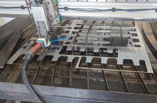
It's alive, I made my first part yesterday Although the metal moved and it was ruined, it wasn't a fault of the table build or the plasma cutter it was a piece of warped metal scrap with welding splatter, and one of the splatters caught the nozzle. I'm very impressed with the PrimeWeld Cut 60Bummer- My FedEx shipment is delayed. it's about 1/2 way here according to the tracking info, it was supposed to arrive today- I hope they didn't loose it. I'm all ready to fire it up when it gets here. I printed what I hope is the right size torch holder for the machine torch, I guess I'll have to wait till it arrives to be certain I printed the right size. I hope it's still on its way and that FedEx didn't loose it 1/2 from NJ to AZ.

Well here are examples of the parts from above drawings. Was wondering if a drawing was done for the x axis trolley? Also note the 2.5" tube jigged up for welding the ends on.Here is an aluminum assembly design concept. Let me know how it works - can be modified as necessary.
BLOCK
PLATE
ASSEMBLY
There is a chamfer / bevel where the blocks meet to allow for welding if that is needed later.


Attachments


Good News everyone! The X motor plate sheet has enough dimensions on it to extrapolate the x trolley print dimensions (approximately)Well here are examples of the parts from above drawings. Was wondering if a drawing was done for the x axis trolley? Also note the 2.5" tube jigged up for welding the ends on.
Attachments
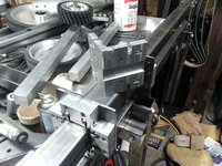
Just wanted to say thanks again for the drawings! My table is just waiting for me to settle on a controller. Have included pics of alternatives to the original design. Notice the gantry Leveling screw in lieu of matched plates on the Y trolly. Also the simple post style belt mounts....saw this on YT. Having printed the entire parts set for a MPCNC before, I was more inclined to try milling the major pieces and quite frankly I have maybe 15 hours total in the alternate parts for this machine. Hopefully these ideas might help others in their builds.....That’s awesome! I don’t remember, I will have go back and dig in my CAD files.
Attachments


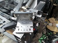
Ive been working on mine here and there when I have the motivation, Wisconsin winters kill me. Ive got my floating Z prototyped and working. I have a to bunch a little stuff to do, and then final assembly and tuning. This setup moves much faster than my ball screw setup so all my gcode code files need to be redone. I'll be ordering a machine torch and THC as well in the near future.
Attachments
CreateStage
Member
- Joined
- Mar 28, 2022
- Messages
- 18
After review it does say to tap the little holes with a 10-32 Hello everyone, the question is regarding the JD's Garage plans (Complete Gantry 2.7), well, I am assuming (you know where that gets us) that on the x-axis arm, do I use nuts to secure the components there? (belt mount idlers) I follow the imperial directions and nowhere does it state to tap with a 10-32 (too thin to tap) or use nuts. I now know it does say to tap the little holes with a 10-32
Has anyone had a problem with these taps? I feel it's too thin to be secure. Thank you!
Slowly but surely assembling my custom 48 x 48" cutting area with the bridge gantry. I am excited to get this machine up and running!
Has anyone had a problem with these taps? I feel it's too thin to be secure. Thank you!
Slowly but surely assembling my custom 48 x 48" cutting area with the bridge gantry. I am excited to get this machine up and running!
Attachments


gpiggaz
Well-known member
I had no problems with the 10-32 threads for the belt idlers on the first one of these I built using a steel Xaxis arm, I am about to make these holes and tap them for the 2nd one I'm building- (Helping the neighbor build in actuality) I don't anticipate any issues here. While the belts are tight, they aren't overwhelmingly tight so the threads don't have to take much force - it's in shear anyway. I suppose if you were really concerned you could try to reach in there and thread a nut onto the screw- but that would be a very painful experience in my opinion.After review it does say to tap the little holes with a 10-32 Hello everyone, the question is regarding the JD's Garage plans (Complete Gantry 2.7), well, I am assuming (you know where that gets us) that on the x-axis arm, do I use nuts to secure the components there? (belt mount idlers) I follow the imperial directions and nowhere does it state to tap with a 10-32 (too thin to tap) or use nuts. I now know it does say to tap the little holes with a 10-32
Has anyone had a problem with these taps? I feel it's too thin to be secure. Thank you!
Slowly but surely assembling my custom 48 x 48" cutting area with the bridge gantry. I am excited to get this machine up and running!
One more piece of advice- for a 48x 48 table, I suggest you make that X axis out of Aluminum. As I said earlier, I built mine with steel, but the neighbor wanted a slightly larger table, so we're building his X axis out of aluminum square stock as suggested in the plans. That should result in more "meat" to get the 10-32 threads into. One final suggesting if you do use Aluminum. You should probably put anti seise on the screws- galling is a real possibility with steel screws and aluminum threads.
Good luck- hope your machine works well- these aren't made for production but they make great hobby machines.
CreateStage
Member
- Joined
- Mar 28, 2022
- Messages
- 18
Wow, very nice! I will have to consider the aluminum bearing blocks after I get mine up and running. Do you guys have CNC mills or are you manually milling these? Or sending them out to a shop?Just wanted to say thanks again for the drawings! My table is just waiting for me to settle on a controller. Have included pics of alternatives to the original design. Notice the gantry Leveling screw in lieu of matched plates on the Y trolly. Also the simple post style belt mounts....saw this on YT. Having printed the entire parts set for a MPCNC before, I was more inclined to try milling the major pieces and quite frankly I have maybe 15 hours total in the alternate parts for this machine. Hopefully these ideas might help others in their builds.....
CreateStage
Member
- Joined
- Mar 28, 2022
- Messages
- 18
Yes, I understand the hobby machine aspect. After looking at some of these more robust machines with aluminum bearing blocks, I am hoping in the future to upgrade mine or just rebuild a bigger, better one. I am mostly concerned about the lengths and accuracy of the belts at 48x48". For now, I will continue with the steel X-axis but that is good advice on both the aluminum and the anti-seize. Thank you. Eventually, I will need a production machine. Whether I buy one, or through this project figure out a way to build one, is the question.I had no problems with the 10-32 threads for the belt idlers on the first one of these I built using a steel Xaxis arm, I am about to make these holes and tap them for the 2nd one I'm building- (Helping the neighbor build in actuality) I don't anticipate any issues here. While the belts are tight, they aren't overwhelmingly tight so the threads don't have to take much force - it's in shear anyway. I suppose if you were really concerned you could try to reach in there and thread a nut onto the screw- but that would be a very painful experience in my opinion.
One more piece of advice- for a 48x 48 table, I suggest you make that X axis out of Aluminum. As I said earlier, I built mine with steel, but the neighbor wanted a slightly larger table, so we're building his X axis out of aluminum square stock as suggested in the plans. That should result in more "meat" to get the 10-32 threads into. One final suggesting if you do use Aluminum. You should probably put anti seise on the screws- galling is a real possibility with steel screws and aluminum threads.
Good luck- hope your machine works well- these aren't made for production but they make great hobby machines.
Did you build a 48x48" cut area version?
Thanks!
gpiggaz
Well-known member
Mine is 28x30. The second machine I’m building is 30x32 cut area. I don’t have a need for anything larger neither does my neighborYes, I understand the hobby machine aspect. After looking at some of these more robust machines with aluminum bearing blocks, I am hoping in the future to upgrade mine or just rebuild a bigger, better one. I am mostly concerned about the lengths and accuracy of the belts at 48x48". For now, I will continue with the steel X-axis but that is good advice on both the aluminum and the anti-seize. Thank you. Eventually, I will need a production machine. Whether I buy one, or through this project figure out a way to build one, is the question.
Did you build a 48x48" cut area version?
Thanks!
I have a Bridgeport clone. So manually.... I think the bearing block could be made on just a drill press (with a good vise) and a vertical band saw. You would want to start with a 1" x 2.5" extruded aluminum bar better than 12" in length. Cutting eight 1.375 blocks and proceed from there.Wow, very nice! I will have to consider the aluminum bearing blocks after I get mine up and running. Do you guys have CNC mills or are you manually milling these? Or sending them out to a shop?
Last edited:
gpiggaz
Well-known member
Finished the neighbor's CNC machine today- had a multitude of self inflicted problems with this one- Last of which was a broken wire in a connector-  Finally got the X, Y and Z axis all working. Still need to install the machine torch- it's on backorder, so I guess we're not "officially" finished, but I'm satisfied we've got it working Funny thing is building the 2nd one actually wasn't bad- Just a few of the same issues with the assembly, but all in all- for hobby use the JD's garage design is quite nice. Might add a roller on the end of the Xaxis arm to get rid of any sag, but for now it seems ok.
While this is basically a clone of the Langmuir - it isn't likely to win any prizes for ruggedness.
I built two of these now- and spent at least $500 on each- but that's mostly because I bought a nice cabinet and some nice connectors which cost about $150 of the total cost. Plus Steel seems to be going up again. Oh well, it was a fun build
Finally got the X, Y and Z axis all working. Still need to install the machine torch- it's on backorder, so I guess we're not "officially" finished, but I'm satisfied we've got it working Funny thing is building the 2nd one actually wasn't bad- Just a few of the same issues with the assembly, but all in all- for hobby use the JD's garage design is quite nice. Might add a roller on the end of the Xaxis arm to get rid of any sag, but for now it seems ok. While this is basically a clone of the Langmuir - it isn't likely to win any prizes for ruggedness.
I built two of these now- and spent at least $500 on each- but that's mostly because I bought a nice cabinet and some nice connectors which cost about $150 of the total cost. Plus Steel seems to be going up again. Oh well, it was a fun build
I found this product some time after I milled my bearing blocks. I might have put money towards this set.

 www.kidchaosconcepts.com
Billet Bearing block for plasma table. | Chaos Concepts
Includes 2 bare bearing blocks and 2 steel weld on mounting plates. Hardware and tube not included.
www.kidchaosconcepts.com
I may upgrade from my Ender3v2 to a Bambu P1S with the extra budget now.
You'll have 1, maybe 2 regrets on that:
- Not having done it faster
- If you don't order the AMS, you'll regret that
I'm looking for mental justification to buy another...you'll like it
You forgot the 3rd, which is how much he will start spending on filament!You'll have 1, maybe 2 regrets on that:
- Not having done it faster
- If you don't order the AMS, you'll regret that
I'm looking for mental justification to buy another...you'll like it
Wow - loving this stuff. I have an E3V2 direct drive, been printing with it for a few years. Also have an Eastwood Versa Cut 40, and want a table… seems like a perfect fit! - or is it? Can anyone confirm if the Eastwood units will work? I’m not sure what info is key to the electronics/interface. Happy to hack into it and add relays or the like if needed.
Thanks!!!
Thanks!!!
Attachments
KwikFab
Well-known member
Wow - loving this stuff. I have an E3V2 direct drive, been printing with it for a few years. Also have an Eastwood Versa Cut 40, and want a table… seems like a perfect fit! - or is it? Can anyone confirm if the Eastwood units will work? I’m not sure what info is key to the electronics/interface. Happy to hack into it and add relays or the like if needed.
Thanks!!!
Any plasma cutter will work on a CNC table as long as it is not high-frequency which causes interference and can potentially **** up your controller.
All that is needed from a plasma cutter to interface with your controller is - a means of a torch ON/OFF which is usually an open circuit, and tapping in for voltage for torch height control reasons (if applicable).
stillnostrebor
Well-known member
The Eastwood is high frequency. I have the same one. Sadly, it is not a good candidate for this project.
rquackenbush
Well-known member
Do you have any info on your plasma table build? I currently run a Crossfire Pro but am interested in making a bigger table.Having built my own 5x10 table from plans I bought, I will tell you that the table is the easiest and cheapest part of a successful CNC plasma table.
Motion control software, drivers, and your plasma source, are what will make it a useful tool.
Do your homework on what makes the table work. Good components are not cheap.
Good luck with your build. I'm along for the ride.