To avoid these ads, REGISTER NOW!

Building a new compressor from scratch

Matt Matt

Well-known member
Joined
May 11, 2017
Messages
523
Location
Ontario
This is my documentary.

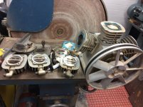
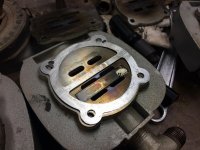
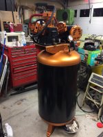
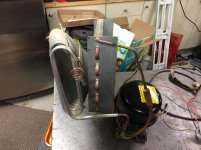
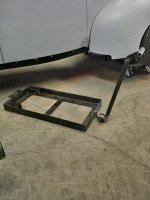
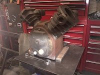
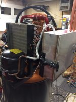
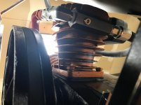
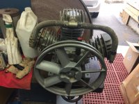
Well I started out with a compressor head pump that was donated to my collection of junk. It was an absolute freebie as it was dismantled from a compressor that no longer worked. I took it home and tore it apart to find out it was just simple reed valves. Some were broken, and some were missed placed. I won't get into that, but the original owner made an attempt at fixing it. He sold the tank and sold the motor, donated the pump to me. This started my rabbit hole. Within the week when I was visiting Homedepot I found some metal strapping just sitting on the floor. How perfect of a material could that be. Took it home for free. This is the start of a fun compressor build from scratch.

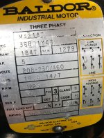
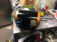
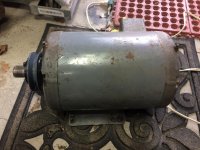
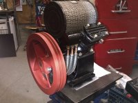
From my research, it needed a five horse power motor and the pump needed to turn at a maximum of 1200 rpm. It is only a single stage three piston high output pump.
 

Attachments

  • IMG_6213.jpg
    IMG_6213.jpg
    143.9 KB · Views: 340
Last edited:
To avoid these ads, REGISTER NOW!

James-W

Well-known member
Joined
Feb 3, 2013
Messages
12,432
Location
Southeastern Wisconsin
If I were you I would just order the right reed valves for that pump. Otherwise you are going to be screwing around and you won't get it working right.

You do realize, if you buy a tank, a 5hp electric motor, and the other stuff needed to build a compressor, you will have almost as much in it as you would if you just went out and bought a compressor.
 
OP
M

Matt Matt

Well-known member
Joined
May 11, 2017
Messages
523
Location
Ontario
If I were you I would just order the right reed valves for that pump. Otherwise you are going to be screwing around and you won't get it working right.

You do realize, if you buy a tank, a 5hp electric motor, and the other stuff needed to build a compressor, you will have almost as much in it as you would if you just went out and bought a compressor.

Well that pump was 20+ years and discontinued. There was a option of buying new heads with reeds, a plug and play assembly, at $60 each....not an option when doing it on the cheep. Banding is a tempered steal. It'll work just fine. I did have to sand the banding to fit.
 

Attachments

  • IMG_6149.jpg
    IMG_6149.jpg
    145.4 KB · Views: 596
  • IMG_6148.jpg
    IMG_6148.jpg
    140.8 KB · Views: 499

Marctrees

Well-known member
Joined
Mar 5, 2015
Messages
6,265
Location
TX/LA border - Toledo Bend
MattMatt I do applaud your creativeness, but Steel banding material for a reed valve???

Multiple forces acting on that piece.., constant flexing, high heat, etc.

You are either WAYY more knowledgeable in Metallurgy and selection of steel recipes than me, or ..ahem... not.

Might work.. for 1 minute, one day, one month.. years?

But I have my doubts. Marc
 

Marctrees

Well-known member
Joined
Mar 5, 2015
Messages
6,265
Location
TX/LA border - Toledo Bend
Another thing is... even if they SEEM to work, but what if you end up w 1/2 the CFM OEM valves would deliver ??

Sure, you can do a pump up time calc, but how do you know they wont change after just an hour?

WAY too questionable unknown experimental for me anyway.

But anything is possible.

If they don't work out, don't think it would damage anything, can always get the new heads down the road. Marc
 
Last edited:

Marctrees

Well-known member
Joined
Mar 5, 2015
Messages
6,265
Location
TX/LA border - Toledo Bend
HOLY BATMAN !!!!!

I just noticed what you have the parts sitting on in the photo.

What is the disk diameter ?

Brand ?

Drooling.

LOVE it !!! Marc
 
Last edited:
OP
M

Matt Matt

Well-known member
Joined
May 11, 2017
Messages
523
Location
Ontario
HOLY BATMAN !!!!!

I just noticed what you have the parts sitting on in the photo.

What is the disk diameter ?

Brand ?

Drooling.

LOVE it !!! Marc
Wadkin JTA 30" thanks, it is a nice machine
 

Attachments

  • IMG_1064.jpg
    IMG_1064.jpg
    19.5 KB · Views: 192

laser3kw

Well-known member
Joined
Nov 17, 2012
Messages
7,276
Location
northen IL
you're in it this far - bite the bullet and get the OEM type replacement reeds. As others have stated, banding material is not a long lasting solution.
 
OP
M

Matt Matt

Well-known member
Joined
May 11, 2017
Messages
523
Location
Ontario
you're in it this far - bite the bullet and get the OEM type replacement reeds. As others have stated, banding material is not a long lasting solution.
yeah, point noted. There was nothing wrong with the heads. And as I've mentioned previously they don't sell the reed valves loose. Now they only sell it as a whole head assembly. At $60 apiece I wasn't about to spend $180. I did consider making up high quality stainless steel ones. Maybe I'll do that when these ones fail.
 
OP
M

Matt Matt

Well-known member
Joined
May 11, 2017
Messages
523
Location
Ontario
So now onto the next part. The air compressor came originally with a two pole 3450 RPM 4.3 hp motor. Well, a few years ago I picked up a 5 hp Baldor three phase 1725 RPM Motor for $40 from a local classified ad. My intentions were to build an RPC using it. I retired that idea with that motor as it was a ODP and I wanted a TEFC. And the bearings were shot in it. So it ended up in the rat hole. So I dug it out and cleaned it up, outfitted it with its original size sheave/pulley 4". I replaced both front and back bearings for about $20. Running a motor with half the speed and the same pulley set up, I didn't realize the 17 CFM pump would be only half the CFM. I was OK with that as I knew I could run the motor at double the speed using a Vfd if I decided to go that route. So had to give it a paint job too, and it would be so much easier well it was a part doing the bearings.
 

Attachments

  • IMG_6746.jpg
    IMG_6746.jpg
    140.4 KB · Views: 155
  • IMG_1080.jpg
    IMG_1080.jpg
    141.8 KB · Views: 160
  • IMG_1071.jpg
    IMG_1071.jpg
    143.6 KB · Views: 147

speed bump

Well-known member
Joined
May 28, 2008
Messages
6,317
Location
Butte Montana
Why not just change pulley sizes and not have to worry about changing speed.

Also from what I remember you need a pretty stout vfd to run a compressor.
 
OP
M

Matt Matt

Well-known member
Joined
May 11, 2017
Messages
523
Location
Ontario
Why not just change pulley sizes and not have to worry about changing speed.

Also from what I remember you need a pretty stout vfd to run a compressor.
A VFD that is specifically designed for a single phase input and three phase output... Will have a requirement/ability to take and transform 200% of a 3 phase motors name plate as a single phase input. There's about a dozen manufactures on the market that have already made this adjustment for single phase input operation. They're not cheap, but I know my option. A industrial three phase input to three phase output VFD needs to be double the size as it's performance is only 66% when derated by using single phase.

The idea of running the pump at half speed or less provides me with more torque and less noise, if recovery was not important. But I had to make sure of is the splash bath was adequately lubricating the Pistons. This pump is a single stage, not a two stage. Single stage pumps require less torque in start up as the unloader usually leaves a pretty empty line with no pressure in it so long as the check valve is working properly.
 
OP
M

Matt Matt

Well-known member
Joined
May 11, 2017
Messages
523
Location
Ontario
The next part is I found now I needed a tank. A brand new 60 gallon tank was going to run me around $250. I opted to sit tight and see what I can find cheaper on the used market. About two weeks passed and I found a 7 year old Campbell Housfeld 80 gallon tank that the motor seized and the guy just wanted it out. He kept the pump and threw away the motor and bought a whole new air compressor. I pulled the bottom drain and scoped it to find no rust. For free, I just counted my lucky stars. I did a dry layout of motor and pump and transferred the new screw locations. I gave it a good clean up and paint job. I have a purchase a few new things. I decided to go with hydraulic line from the pump. I picked up a new check valve, a few ball valves, A pressure relay and 200 psi pressure gauge. I pulled the butterfly valve well doing the scope and replaced it with a more assessable ball valve. All these pieces ran me about $100.
 

Attachments

  • IMG_1065.jpg
    IMG_1065.jpg
    138.7 KB · Views: 253
  • IMG_1066.jpg
    IMG_1066.jpg
    144.8 KB · Views: 264
  • IMG_1078.jpg
    IMG_1078.jpg
    142 KB · Views: 279
  • IMG_1081.jpg
    IMG_1081.jpg
    141.9 KB · Views: 283
  • IMG_1084.jpg
    IMG_1084.jpg
    142.4 KB · Views: 294
  • IMG_1090.jpg
    IMG_1090.jpg
    126.3 KB · Views: 252
  • IMG_1089.jpg
    IMG_1089.jpg
    132.6 KB · Views: 253

LXCam

ALLIANCE MEMBER
Joined
Apr 23, 2013
Messages
19,075
Location
AZ
I'm thinking ole Matt Matt here is a tad bit more resourceful then you guys are giving him credit for. I'm watching :p
 
OP
M

Matt Matt

Well-known member
Joined
May 11, 2017
Messages
523
Location
Ontario
So with a temporary VFD set up I ran it up to speed. I filled the tank up at 60 Hz and it took 24 minutes and 31 seconds from completely empty to 155 psi. At 6 feet it recorded 80 Hz decibel, and the single phase amp draw at 230 V varied (from empty to full) from 3 A and ended at 5.5A

I repeated the test with the motor spinning at double the speed 120 Hz and it took 11 minutes and 3 seconds. It recorded 88 Hz decibel. At empty lower end I was reading 6.5 and just before it shut off at 155 psi it was reading 13.2 A. The bearings that I purchased had a maximum reading on them of 5000 RPM. So I believe I could probably spend this motor up to 150 Hz and still be fine, but I'm just playing safe for now.

After filling it, and emptying it three times, I thought I would leave it at the 155 psi cut off (fully charged) for a few days to see a pressure test and check for leaks. It didn't budge at all. The tank has a test rating tag of 200 psi at 400°F. I didn't really analyze the tag information that much as I think I'm within safe operation.

The only problem that bothers me is that after filling it three times I emptied about a half a quart of water from the bottom drain. So it was time to figure out how to stop that from happening or at least reduce it. Off to the drawing board
 

Attachments

  • IMG_6747.jpg
    IMG_6747.jpg
    146.7 KB · Views: 126
Last edited:
To avoid these ads, REGISTER NOW!
OP
M

Matt Matt

Well-known member
Joined
May 11, 2017
Messages
523
Location
Ontario
Mattmatt - Pump ID info if you got it please. Marc
There is actually no tags or information on the pump at all. There is a little silly sticker that had cast-iron pump which I removed when I painted. But there is no specs on it at all. The best I did was checked the bore and stroke (when the heads were off) and compared it to a model that had the exact same bore and stroke. So I'm a little empty-handed here.

This is all I have to go by.
 

Attachments

  • IMG_1148.jpg
    IMG_1148.jpg
    8.8 KB · Views: 151
Last edited:
OP
M

Matt Matt

Well-known member
Joined
May 11, 2017
Messages
523
Location
Ontario
Worst case, if you don't have that.. then just a photo close up of that front of the crankcase.. The side w the brass drain elbow and the sight glass. Marc

This is the best information I've been able to pull up.


DETAILS
Feature(s)

Cast iron pump, hi flo 3 cylinder, oil-lubricated, includes flywheel and filters.
Application(s)


Weight & Package Dimensions

Weight (lbs) 83.63
Package (L x W x H) 23.2 x 23.2 x 17.0 in.
Attributes & Specifications

Type Single Stage Air Compressor Pump
gal.
Max. Pressure 155 PSI
Pump Stages 1
Max. RPM 1,250 RPM
Horsepower (Running) 4.7 HP
RPM Range 1,150 to 1,250 RPM
Number of Cylinders 3
Stroke Length 1.89 in.
Pump Oil Capacity 33 oz
Flywheel Diameter 12 in.
Bore Diameter 2.56 in.
V-Belts A
Delivered CFM 16.1 CFM @ 40 PSI / 14.0 CFM @ 90 PSI
CFM Delivered @ 40 PSI 16.1 CFM
CFM Delivered @ 90 PSI 14.0 CFM
CFM Delivered @ 100 PSI 13.9 CFM
CFM Delivered @ 175 PSI n/a CFM
Accessories Uses 3 canister type air filters.
For Use With 8367401 ACCESSORIES REVIEWS Q & A MANUALS & PARTS
Recently Viewed

4.7 HP Single Stage Air Compressor Pump
 

Dragoonmc

Well-known member
Joined
Feb 5, 2015
Messages
60
What paint are using for this? I love the color combo


Sent from my iPhone using Tapatalk
 
OP
M

Matt Matt

Well-known member
Joined
May 11, 2017
Messages
523
Location
Ontario
I do have a bad habit of taking things for free to fix up, or salvage for parts. So I do like going to auctions of all types. I picked up this dehumidifier for $.50. So now I was determined to make a pre-chiller to get rid of the moisture. And if when I got home, it didn't work, no big deal. So when I tested it the fan motor was on it's last leg. The condenser, pump and evaporator work perfect. Time to repurpose another piece of junk.
 

Attachments

  • IMG_1095.jpg
    IMG_1095.jpg
    142.5 KB · Views: 161
  • IMG_1094.jpg
    IMG_1094.jpg
    140.9 KB · Views: 164
  • IMG_1093.jpg
    IMG_1093.jpg
    139.7 KB · Views: 163
  • IMG_1088.jpg
    IMG_1088.jpg
    128.9 KB · Views: 156
  • IMG_1085.jpg
    IMG_1085.jpg
    140.8 KB · Views: 167
OP
M

Matt Matt

Well-known member
Joined
May 11, 2017
Messages
523
Location
Ontario
I pulled out as much copper pieces as I had in stock. I did have to run out and buy a 12 foot piece of half-inch copper. I started braising up my chiller. My intentions were to build a miniature freezer filled with glycol and pull the moisture out of the air before it dropped into the tank. I pitched in a wood fixture to keep the pipes in place well I soldered. I knew I had to split the wood after it was completely soldered as it would be handcuffed on. I did have two joints that leaked. No big deal, I guess that's why I did the pressure test.
 

Attachments

  • IMG_1119.jpg
    IMG_1119.jpg
    152.9 KB · Views: 189
  • IMG_1115.jpg
    IMG_1115.jpg
    137.8 KB · Views: 200
  • IMG_1109.jpg
    IMG_1109.jpg
    143.2 KB · Views: 168
  • IMG_1105.jpg
    IMG_1105.jpg
    133.2 KB · Views: 170
  • IMG_1099.jpg
    IMG_1099.jpg
    143.2 KB · Views: 182
  • IMG_1098.jpg
    IMG_1098.jpg
    141.9 KB · Views: 164
  • IMG_1096.jpg
    IMG_1096.jpg
    138.7 KB · Views: 163

isb cornbinder

Well-known member
Joined
Nov 3, 2010
Messages
7,073
Location
Pacific South West, BC, Canada
I also built my compressor from pieces. It started with buying an Ingersoll T30, in pieces including a master rebuild kit. I bought the a new Ingersoll 80 gallon tank and a Baldor motor from a swimming pool contractor in Shelter Cove. The compressor was $25, the tank was another $100 and the motor was another $100. I built the mobile base. This unit really pounds out the air. I cannot truthfully say it is quiet, but, I do not mind because it comes on and builds air rapidly and shuts off. This compressor will keep 115 psi ahead of my blast cabinet.
I picked up the smaller red compressor at "Curb-Mart). It was sitting on the curb with a free sign. There was a loose pipe plug in the intake making the compressor very slow. I took the plug out, and added a filter. This curb-mart compressor is no big performer, but it builds air quickly and make a terrible noise, about twice as loud as the T30
 

Attachments

  • MOD-U-BLAST CABINET.jpg
    MOD-U-BLAST CABINET.jpg
    64.3 KB · Views: 123
  • MOBILE BASE SOLUTION.jpg
    MOBILE BASE SOLUTION.jpg
    104.5 KB · Views: 130
  • Ingersol T30 front3~4 view.jpg
    Ingersol T30 front3~4 view.jpg
    52 KB · Views: 150
  • Ingersol T30 80.jpg
    Ingersol T30 80.jpg
    52.4 KB · Views: 150
  • AIR COMPRESSOR FROM CURB-MART.jpg
    AIR COMPRESSOR FROM CURB-MART.jpg
    85 KB · Views: 151
  • INGERSOL T30 80 WITH MOBILE BASE.jpg
    INGERSOL T30 80 WITH MOBILE BASE.jpg
    63.6 KB · Views: 144
  • Ingersol 2 stage.jpg
    Ingersol 2 stage.jpg
    24 KB · Views: 136
OP
M

Matt Matt

Well-known member
Joined
May 11, 2017
Messages
523
Location
Ontario
What paint are using for this? I love the color combo


Sent from my iPhone using Tapatalk
The black on the tank trimclad semi gloss
The black and rust colours Iused a rattle can high temperature spray paint made by VHT. It's designed for engine blocks to a maximum temperature of 600°F.
 

kbs2244

Well-known member
Joined
Nov 11, 2006
Messages
14,065
Location: Ontario/Florida
Anyone who can do this is one up one me

But, in my experience, reed valves haven't changed in decades, and are bought by OEMs by the truck load.

If you can find the PN off one of the originals you should be able to find the actual mfg.
I would be a cup of coffee they can be bought new.
 
OP
M

Matt Matt

Well-known member
Joined
May 11, 2017
Messages
523
Location
Ontario
Location: Ontario/Florida
Anyone who can do this is one up one me
About seven years ago, you too could buy a trailer park home in Florida for less than a brand new pick up truck. What can I say? I like the cross-border shop and 20 feet of snow removal is for the young at heart. We call this snowbirds. http://www.cbc.ca/news/politics/canadian-snowbirds-8-months-1.4011788

So for my new chiller I had to make up some 3 custom brass Y's . I just took some 1"x1"x2" and drilled and tapped in three 3/8 NPT. One for the intake, one for the exhaust and one to remove the condensed water vapour. I also welded up a little stainless steel box and insulated it with half inch pink Styrofoam. Then I dry fit the dehumidifier evaporator and my new homemade condenser/chiller.
 

Attachments

  • IMG_1129.jpg
    IMG_1129.jpg
    139.3 KB · Views: 174
  • IMG_1130.jpg
    IMG_1130.jpg
    133.3 KB · Views: 174
  • IMG_1122.jpg
    IMG_1122.jpg
    133.4 KB · Views: 146
  • IMG_1123.jpg
    IMG_1123.jpg
    133.8 KB · Views: 145
  • IMG_1142.jpg
    IMG_1142.jpg
    131.6 KB · Views: 154
  • IMG_1117.jpg
    IMG_1117.jpg
    134.3 KB · Views: 145
  • IMG_1116.jpg
    IMG_1116.jpg
    138 KB · Views: 147
Last edited:
OP
M

Matt Matt

Well-known member
Joined
May 11, 2017
Messages
523
Location
Ontario
So the next part was to weld up a angle iron bracket for the new chiller unit and the future VFD and box. I also had to pick up another hydraulic line as the one that used to drop into the tank is now dropping into the chiller so I now needed one from the chiller back to the tank.
 

Attachments

  • IMG_1146.jpg
    IMG_1146.jpg
    143.9 KB · Views: 141
  • IMG_1145.jpg
    IMG_1145.jpg
    130.6 KB · Views: 169
  • IMG_1141.jpg
    IMG_1141.jpg
    147.8 KB · Views: 173
  • IMG_1140.jpg
    IMG_1140.jpg
    146.6 KB · Views: 163
  • IMG_1133.jpg
    IMG_1133.jpg
    141.2 KB · Views: 156
  • IMG_1132.jpg
    IMG_1132.jpg
    133.6 KB · Views: 156
  • IMG_1118.jpg
    IMG_1118.jpg
    145.4 KB · Views: 159
OP
M

Matt Matt

Well-known member
Joined
May 11, 2017
Messages
523
Location
Ontario
Well damn, Matt you have Me hooked !

I will be watching this !
Thanks. A lot of the stuff I usually work on is an acquired taste to others. Usually there isn't much interest. I try not to be a consumer as much as possible. I know I could've ran out and bought a brand new air compressor with about the same specs for $12-$1500. And I could've bought a professionally built chiller for about the same price. But, I think I would've wasted my skills and not learned anything new along the way.
 
OP
M

Matt Matt

Well-known member
Joined
May 11, 2017
Messages
523
Location
Ontario
So tonight, I filled up the chiller unit with a glycol RV plumbing anti-freeze. I did test it first to see if it would dissolve the foam for three days. For my tests prior, I was just using plain old tapwater, but within 10 minutes it was starting to freeze. The first zero to full cycle (shut down at 155 psi) the chiller removed about half a cup of water. So far, There is nothing to be found in the tank. I painted a flat black on the stainless steel chiller box just to match the theme.

I did modify this in-line check valve prior to the chiller. I drilled in tapped it for 1/4 NPT. I plan on using it as a pressure relief for cycle completion, so I'm not unloading the pressure in the chiller too.
 

Attachments

  • IMG_6752.jpg
    IMG_6752.jpg
    143.7 KB · Views: 128
  • IMG_6754.jpg
    IMG_6754.jpg
    140.5 KB · Views: 162
  • IMG_6756.jpg
    IMG_6756.jpg
    133.9 KB · Views: 141
  • IMG_6755.jpg
    IMG_6755.jpg
    138.5 KB · Views: 156
Last edited:

LS6 Tommy

Well-known member
Joined
Dec 27, 2013
Messages
26,162
Location
Northern NJ
you're in it this far - bite the bullet and get the OEM type replacement reeds. As others have stated, banding material is not a long lasting solution.

Although your posts so far lead me to the impression that you are FAR from being a hack, I'm on board with this logic, too. Most reeds are high carbon steel. Some older ones were brass or stainless. If you really want to go DIY, shim stock is usually a good bet for making your own reeds.

Metal banding is brittle and will work harden and break quickly. I can break it with my bare hands just from flexing it to the point of a fatigue fracture. If bits of it get down into the cylinder, they can score the walls, wipe out the rings or beat up the piston. If the pump is as old as you say, good luck finding those parts cheaply (or at all).

Tommy
 
Last edited:

MagKarl

Well-known member
Joined
Oct 15, 2012
Messages
684
Location
Olympia, WA
You guys hung up on the reeds are missing the boat. I think Ol' Matt here has a wealth of knowledge and skills that we're just getting a glimpse of.
 
To avoid these ads, REGISTER NOW!
Top Bottom