To avoid these ads, REGISTER NOW!

Built me a Buffer

Jim Stabe

Well-known member
Joined
Feb 18, 2009
Messages
801
Location
San Diego, Ca
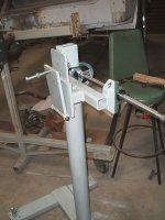
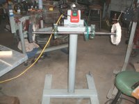
I wanted a buffer so I could polish all the forged aluminum C4 Corvette suspension pieces that I am using on my MG project. True to my frugal nature, I didn't want to spend $400-$500 for the commercially available ones so I built this one mostly from stuff I had in the shop already. The width of the base was set by the length of a scrap of 2" x 5" x 1/4" tubing (around 24") the legs were cut from some 4" channel. The feet, which you can't see in the picture, are hockey pucks that are turned down and pressed into short lengths of 3" od tubing. One of the feet is adjustable height so it can compensate for uneven floors. The vertical piece is the last piece of a 4" pipe that has provided support for several of my other tools. I did have to buy the pillow blocks that were $8 each from Northern Tool and the safety switch was a cheapie from Grizzly (I bought 3 when they were on sale a couple years ago). I also spent $8 for the 1" cold rolled material for the shaft. I saw how much a 3/4" left hand die cost so I learned how to single point a 3/4" left hand thread on my lathe and it turned out pretty nice.

The motor is a 1 1/2 hp 3450 rpm that used to be on a table saw. The buffs are cheap HF but will be replaced with some 10" Caswell soon.

Buffer 003.jpg

Buffer 004.jpg

Buffer 001.jpg
 
To avoid these ads, REGISTER NOW!

Mickey O

Well-known member
Joined
Oct 25, 2009
Messages
6,153
Location
Chicago, IL
Nice job, I'd love a dedicated buffing machine, and don't worry about the guard, these days they can reattach lost digits with no problems.
 
OP
J

Jim Stabe

Well-known member
Joined
Feb 18, 2009
Messages
801
Location
San Diego, Ca
Nice job, I'd love a dedicated buffing machine, and don't worry about the guard, these days they can reattach lost digits with no problems.
If I don't do a guard I would still have to mount a basket to catch the fingers so I could take them to the emergency room - might as well do a guard.
 

LoneGunman

Well-known member
Joined
Mar 27, 2007
Messages
2,081
Location
The Gunshine state
Any wobble? I was thinking about doing the same thing, the only difference was I was thinking about buying a piece of ground and hardened piece of 3/4" for the shaft.
 
OP
J

Jim Stabe

Well-known member
Joined
Feb 18, 2009
Messages
801
Location
San Diego, Ca
Any wobble? I was thinking about doing the same thing, the only difference was I was thinking about buying a piece of ground and hardened piece of 3/4" for the shaft.
Save your money and use cold rolled. The shaft runs very true and even if it was out slightly, the buffs are not that round or balanced. I would use a 1" shaft and turn down the ends to whatever diameter you want for the threads.
 
OP
J

Jim Stabe

Well-known member
Joined
Feb 18, 2009
Messages
801
Location
San Diego, Ca
For those concerned with my fingers here are the guards I made for it. They are 1/8" steel and very substantial. The 1 1/2 hp motor also gave up so I replaced it with a 1 hp Craftsman I had. The 1 hp motor weighs 15 lbs more than the 1 1/2 hp and is at least a couple inches larger in diameter. The 1 hp has a shaft on either end so I set up the right side to run at 7100 sfpm and moving the belt to the left gives 3600 sfpm. The whole machine weighs 190 lbs.
Buffer 009.jpg

Buffer 010.jpg
 
Last edited:

nolatoolguy

Banned
Joined
Jan 11, 2010
Messages
1,065
Location
Louisiana
Wow looks pretty good. I like how the wheels arent put to close to the motor. Theres alot of room to move parts and objects around on the wheel without the motor being in the way. Probably alot better built then if you to buy one at homedepot or sears etc
 

Zrexxer

Well-known member
Joined
Jan 23, 2007
Messages
5,058
Location
Pflugerville, TX
Not that your design isn't 100% workable, but why did you decide to run two belt setups instead of stepped sheaves and one belt?
 
To avoid these ads, REGISTER NOW!

hilld

Well-known member
Joined
Jan 19, 2010
Messages
867
Location
Vancouver, WA & San Juan Island, WA
The 1 hp has a shaft on either end so I set up the right side to run at 7100 sfpm and moving the belt to the left gives 3600 sfpm.

The only problem I can see with that setup is when you use the other side of the motor for the second speed, the rotation of the buffing wheels will be in reverse - something to consider.
 
OP
J

Jim Stabe

Well-known member
Joined
Feb 18, 2009
Messages
801
Location
San Diego, Ca
Not that your design isn't 100% workable, but why did you decide to run two belt setups instead of stepped sheaves and one belt?
I had everything to do it that way, I would have had to buy stepped pulleys at $20+ apiece and I don't think they even make stepped pulleys in 1' bore
 
Last edited:
OP
J

Jim Stabe

Well-known member
Joined
Feb 18, 2009
Messages
801
Location
San Diego, Ca
The only problem I can see with that setup is when you use the other side of the motor for the second speed, the rotation of the buffing wheels will be in reverse - something to consider.
Think about it - You will realize that the wheels will rotate the same direction driven from either end of the motor.
 

akdiesel

Well-known member
Joined
Aug 8, 2008
Messages
2,617
Location
Wasilla, AK
You made a product that looks good enough to sell to the public. Being on an HSE board I give you an A+ on the guards as well.
How log does it take you to change belts?
 

Brad54

Well-known member
Joined
Jun 13, 2006
Messages
4,646
For those concerned with my fingers here are the guards I made for it. They are 1/8" steel and very substantial. The 1 1/2 hp motor also gave up so I replaced it with a 1 hp Craftsman I had. The 1 hp motor weighs 15 lbs more than the 1 1/2 hp and is at least a couple inches larger in diameter. The 1 hp has a shaft on either end so I set up the right side to run at 7100 sfpm and moving the belt to the left gives 3600 sfpm. The whole machine weighs 160 lbs.
Buffer 009.jpg

Buffer 010.jpg

Neat. You've definitely inspired me to make something similar!
Nice that you have two different speeds, too. I'd have to do some digging, but I believe stainless gets polished at a different rpm than aluminum. Don't remember why, but I believe that was the case. You came up with a pretty elegant solution there.

Do you have any issues with the machine moving while you're working with it? Or is the base stout enough that it won't move when you put pressure on the wheels?

-Brad
 
OP
J

Jim Stabe

Well-known member
Joined
Feb 18, 2009
Messages
801
Location
San Diego, Ca
You made a product that looks good enough to sell to the public. Being on an HSE board I give you an A+ on the guards as well.
How log does it take you to change belts?
Thanks. I haven't timed a belt change but it's probably under 5 minutes, less if you don't start the clock until I have all the tools out and ready to go. Remove the (4) 1/2" bolts that hold the guards on, loosen the jamb nut on the tension bolt, right belt off and left belt on, re-tension and re-install guards. If I was running production I would probably have designed something to speed that up but it works fine for as often as I will be changing speeds.
 
OP
J

Jim Stabe

Well-known member
Joined
Feb 18, 2009
Messages
801
Location
San Diego, Ca
Neat. You've definitely inspired me to make something similar!
Nice that you have two different speeds, too. I'd have to do some digging, but I believe stainless gets polished at a different rpm than aluminum. Don't remember why, but I believe that was the case. You came up with a pretty elegant solution there.

Do you have any issues with the machine moving while you're working with it? Or is the base stout enough that it won't move when you put pressure on the wheels?

-Brad
I wish I could claim that I did the 2 speed thing on purpose but the reality is that the original motor I had stopped working and I needed a replacement. The only motor I had was this old Craftsman 1 hp from the 50's and it had a shaft on each end. Lucky me I thought since the motor wasn't reversible I could mount it upside down if it didn't spin the right direction. After I got it mounted up it hit me that I could use the other end for a low speed if I just cut another keyway in the buffer shaft and mounted another pulley. The motor already had a 2 1/2" pulley on that end and I had a 5" pulley with a 1" bore. Volia, I had a low speed.

The machine weighs 190 lbs and I have feet that I made out of hockey pucks that grip the floor pretty well. Result is that it doesn't move at all even when I'm pushing hard and the machine doesn't vibrate at all.
 
Last edited:

tcianci

Well-known member
Joined
Feb 7, 2009
Messages
4,242
Location
Walpole, Ma
Hey, what if you split the shaft in the middle, and sleeved it back together with a bronze bushed sleeve. Then you could have two speeds at the same time!
 
OP
J

Jim Stabe

Well-known member
Joined
Feb 18, 2009
Messages
801
Location
San Diego, Ca
Hey, what if you split the shaft in the middle, and sleeved it back together with a bronze bushed sleeve. Then you could have two speeds at the same time!
There is about 8" of overhang outside the pillow blocks to allow working room around the buffs. Cutting the shaft in the middle and using a sleeve would cut the bearing span supporting the shaft in half and I fear might cause some instability at the outer end of the shafts. I actually use the high speed all the time for polishing aluminum and stainless pieces and only have the low speed available if I would need to polish some plastic or very soft metals. It only takes a couple minutes to change the speed over so it isn't much of an inconvenience.
 
To avoid these ads, REGISTER NOW!
Top Bottom