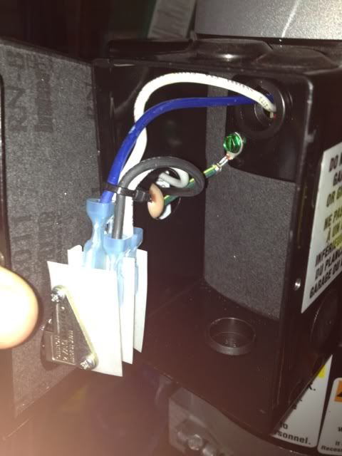
The push button switch appears to be a double pole switch, since they have run both hots from the motor to the switch and then out of the switch. This is NOT what your wiring diagram shows.
The overhead switch need only interrupt one of the hots to shut down the motor. What I would do to save changing a bunch of wires around to conform to the wiring diagram is to bring the wire from the overhead switch into one of the knockouts in the top of the switch box, my lift and most I've seen use SO cord provided by the lift manufacturer.. Pull one of the wires you have in your hand in the second pic, lets say the white one, back into the box and connect it to the black wire from the overhead switch. Then take the white wire from the overhead switch and pull it out of the box, in place of the one you now have sticking out, and then connect your 240v hots to those two (which you will actually do INSIDE the box).
This leaves the push button switch interrupting both of the hots, and the overhead interrupting one of the hots, wired in series with one side of the push button switch.
My Challenger lift is wired like your schematic with a single pole push button switch making the connection on one hot (NO switch) and the overhead switch breaking the other hot when the car is lifted too high (NC switch).
My Challenger also uses rather small wire to the overhead switch, and I wondered about this, but finally reasoned what Strawberry said, its intermittent duty, not running over about 90 seconds at a time max, so it just don't matter.
Charles