To avoid these ads, REGISTER NOW!

Circuits are Trippin'

Kristang

Well-known member
Joined
Sep 2, 2018
Messages
92
Location
Minneapolis
I just finished wiring my new garage. I went outside, turned on the main breaker. I go inside, turn on the breaker in the panel, flip the first breaker and it immediately kicks. I turn on the next breaker, it stays on for a few seconds and it trips. I continue to turn on all the breakers and they ALL trip. I am thinking I must have an issue with the power coming into the building since they are all tripping. Is it possible the power company hooked up the meter incorrectly or maybe something else I did wrong? I was careful to make sure my power leads were marked when I installed them to the panel.
 
To avoid these ads, REGISTER NOW!

mm08822

Well-known member
Joined
Jan 13, 2012
Messages
6,022
Location
NJ
Turn off all branch cb's and the main cb's
Unplug anything possible and turn off all switches
Measure all voltages on line side of outdoor main cb
  • L1-L2 = 240V?
  • L1 - N = 120v?
  • L2-N = 120V?
Turn on outdoor cb if you get the above readings
Repeat readings progressively working your way inside to the panel buss.

Pick a ckt that has a recept on it close by to panel w/o anything plugged in. Does the gfci reset? Measure h-n. H-G should trip it (maybe)

What type of cb's are tripping? gfci's, afci's, standard cb's.....?

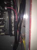
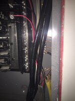
Take a pic of main disc and panel with covers off.
 
Last edited:
OP
K

Kristang

Well-known member
Joined
Sep 2, 2018
Messages
92
Location
Minneapolis
Turn off all branch cb's and the main cb's
Unplug anything possible and turn off all switches
Measure all voltages on line side of outdoor main cb
  • L1-L2 = 240V?
  • L1 - N = 120v?
  • L2-N = 120V?
Turn on outdoor cb if you get the above readings
Repeat readings progressively working your way inside to the panel buss.

Pick a ckt that has a recept on it close by to panel w/o anything plugged in. Does the gfci reset? Measure h-n. H-G should trip it (maybe)

What type of cb's are tripping? gfci's, afci's, standard cb's.....?


Take a pic of main disc and panel with covers off.

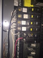
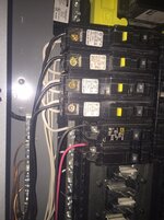
Thank you. Here are pics of both panels.
 

Attachments

  • Panel1.jpg
    Panel1.jpg
    108.3 KB · Views: 227
  • Panel2.jpg
    Panel2.jpg
    85 KB · Views: 238

mm08822

Well-known member
Joined
Jan 13, 2012
Messages
6,022
Location
NJ
Did you read the voltages of the incoming supply?

This is where conductor identification is important.
Neutrals shall be identified as white and grounds as green. Required by code (and helps to get it wired correctly the first time.)
You could also mark one hot leg with red or a band of blk tape but not so important.Just land them both on the cb.

I would turn of the outside main and verify each conductor terminates where it should in the panel. Do nothing else first.
 

mm08822

Well-known member
Joined
Jan 13, 2012
Messages
6,022
Location
NJ
You also need a grounding electrode conductor and 2 grd rods connected to the exterior disconnect neutral bar.

Inside Pic is too dark..
On the inside panel -
are there only ground wires (bare or green) on the left ground bar?
are there only neutral wires (white) on the right neutral bar?
 
Last edited:
OP
K

Kristang

Well-known member
Joined
Sep 2, 2018
Messages
92
Location
Minneapolis
You also need a grounding electrode conductor and 2 grd rods connected to the exterior disconnect neutral bar.

Inside Pic is too dark..
On the inside panel -
are there only ground wires (bare or green) on the left ground bar?
are there only neutral wires (white) on the right neutral bar?


There is a ground bar on each side of the interior panel. Only bare wire on those. I have two ground rods attached to the interior panel, however, I have no ground rod attached to the outside/exterior panel. I am not home from work yet so I have not attempted to read the voltage.


Sent from my iPhone using Garage Journal
 
OP
K

Kristang

Well-known member
Joined
Sep 2, 2018
Messages
92
Location
Minneapolis
You also need a grounding electrode conductor and 2 grd rods connected to the exterior disconnect neutral bar.

Inside Pic is too dark..
On the inside panel -
are there only ground wires (bare or green) on the left ground bar?
are there only neutral wires (white) on the right neutral bar?


c2e7a4324e480d02ed031320752f2b7f.jpg2c7fffc18a19f997cd800402634a3077.jpg
7b487e06f970c79b35d64f2b1a8b82f3.jpg


Sent from my iPhone using Garage Journal
 

Attachments

  • c2e7a4324e480d02ed031320752f2b7f.jpg
    c2e7a4324e480d02ed031320752f2b7f.jpg
    482.1 KB · Views: 0
  • 2c7fffc18a19f997cd800402634a3077.jpg
    2c7fffc18a19f997cd800402634a3077.jpg
    552.6 KB · Views: 0
OP
K

Kristang

Well-known member
Joined
Sep 2, 2018
Messages
92
Location
Minneapolis
There is a ground bar on each side of the interior panel. Only bare wire on those. I have two ground rods attached to the interior panel, however, I have no ground rod attached to the outside/exterior panel. I am not home from work yet so I have not attempted to read the voltage.


Sent from my iPhone using Garage Journal


My voltage meter is MIA. I will get it back tomorrow and check.


Sent from my iPhone using Garage Journal
 

Jim greengo

Well-known member
Joined
Sep 3, 2018
Messages
7,415
Location
Behind my house
Did you read the voltages of the incoming supply?

This is where conductor identification is important.
Neutrals shall be identified as white and grounds as green. Required by code (and helps to get it wired correctly the first time.)
You could also mark one hot leg with red or a band of blk tape but not so important.Just land them both on the cb.

I would turn of the outside main and verify each conductor terminates where it should in the panel. Do nothing else first.
What he said.:beer::beer::beer::beer:
 

mm08822

Well-known member
Joined
Jan 13, 2012
Messages
6,022
Location
NJ
There is a ground bar on each side of the interior panel. Only bare wire on those. I have two ground rods attached to the interior panel, however, I have no ground rod attached to the outside/exterior panel. I am not home from work yet so I have not attempted to read the voltage.


Sent from my iPhone using Garage Journal

Looks different now! Ok.

I still don't see any color markings on the wires.

The grd rods need to connect to the exterior disconnect neutral bar, not at the interior panel. That is where the bonding screw is.

Did you use a bonding screw in the interior panel?

There are 6 gfci cb's. each tripped? Anything plugged in to those ckts?
Did the 3 2pole 30a cb's trip?

What size wire is the 3 conductor uf cable? what do they feed?
 

mm08822

Well-known member
Joined
Jan 13, 2012
Messages
6,022
Location
NJ
Ummm, the neutrals on the gfci circuits look to be landed on the neutral bar.

Homeline_GFCI.JPG
 
Last edited:

MattT

Well-known member
Joined
Feb 20, 2010
Messages
3,201
What do you mean?

It looks like the load side neutral terminals on your breakers are daisy chained and tied to the neutral bar. Those terminals are supposed to be connected to the neutral wires going out to your receptacles.

Also it looks like you've got plug on, line side, neutral breakers but I'm not sure whether that is a plug on neutral panel??

Not to be ugly or anything but I think you need professional help with this.
 

AntonLargiader

Well-known member
Joined
Nov 20, 2016
Messages
1,372
Location
Charlottesville, VA
I think I see neutrals landed on the breakers and the pigtails trimmed and landed on the neutral bar, but I also see three neutrals on each side with four breakers on one side and two on the other so I can’t tell what neutral lands where. The neutral from each circuit must be on the same breaker as its black is.
 

MattT

Well-known member
Joined
Feb 20, 2010
Messages
3,201
I think I see neutrals landed on the breakers and the pigtails trimmed and landed on the neutral bar, but I also see three neutrals on each side with four breakers on one side and two on the other so I can’t tell what neutral lands where.

The "missing" left side neutral is landed on the neutral bus just below the DP 30A. You can tell it's from the rightmost 12G romex on the left side of the panel. And that is one of the 4 circuits landed on those left side AFCI breakers.
 

klassenl

Well-known member
Joined
Feb 20, 2016
Messages
715
Location
Southern Alberta
It appears that those breakers are GFCI breakers. If so the white and the black both have a screw on the breaker. The black on the top screw and the white on the screw underneath.
 
To avoid these ads, REGISTER NOW!

mm08822

Well-known member
Joined
Jan 13, 2012
Messages
6,022
Location
NJ
It appears that those breakers are GFCI breakers. If so the white and the black both have a screw on the breaker. The black on the top screw and the white on the screw underneath.

If you zoom in on the pics it shows a gfci label for all 6 1p cb's.

It is easiest to see on the lefthand set of cb's that the gfci cb's do not have a load neutral connected on the cb. Also looks like the 18" curly q was trimmed down significantly and terminated on the neutral buss - no problem with that.

The neutral connection from the cb exits on the underside of the cb. That is the same "depth" that the branch circuit neutrals appear "connect" to the cb. However the branch circuit's neutral is connected to the neutral bar under each cb.

OP has to re-land the respective neutrals onto the respective gfci neutral connection points.

I doubt the 2p 30a cb's tripped even though all cb's were initially reported as tripped. Changes the story quickly.
 

AntonLargiader

Well-known member
Joined
Nov 20, 2016
Messages
1,372
Location
Charlottesville, VA
Yep... I had a spare Homeline GFCI breaker downstairs and looking at it it seems that there actually are no neutrals landed on his.

Now, is everything else tripping also, or just the GFCIs?
 

dave*99

Well-known member
Joined
May 5, 2009
Messages
4,274
Location
Coastal NJ
If you zoom in on the pics it shows a gfci label for all 6 1p cb's.

It is easiest to see on the lefthand set of cb's that the gfci cb's do not have a load neutral connected on the cb. Also looks like the 18" curly q was trimmed down significantly and terminated on the neutral buss - no problem with that.

The neutral connection from the cb exits on the underside of the cb. That is the same "depth" that the branch circuit neutrals appear "connect" to the cb. However the branch circuit's neutral is connected to the neutral bar under each cb.

OP has to re-land the respective neutrals onto the respective gfci neutral connection points.

I doubt the 2p 30a cb's tripped even though all cb's were initially reported as tripped. Changes the story quickly.

This. :thumbup:
 
OP
K

Kristang

Well-known member
Joined
Sep 2, 2018
Messages
92
Location
Minneapolis
If you zoom in on the pics it shows a gfci label for all 6 1p cb's.

It is easiest to see on the lefthand set of cb's that the gfci cb's do not have a load neutral connected on the cb. Also looks like the 18" curly q was trimmed down significantly and terminated on the neutral buss - no problem with that.

The neutral connection from the cb exits on the underside of the cb. That is the same "depth" that the branch circuit neutrals appear "connect" to the cb. However the branch circuit's neutral is connected to the neutral bar under each cb.

OP has to re-land the respective neutrals onto the respective gfci neutral connection points.

I doubt the 2p 30a cb's tripped even though all cb's were initially reported as tripped. Changes the story quickly.[/QUOTE

I did not turn the 30 amp CB's yet, only the GFCI's. Sounds like you guys figured out I have the wires from the GFCI's landed in the wrong location?
 

Norcal

Well-known member
Joined
Mar 16, 2008
Messages
13,767
If the neutral pigtail is connected but there is no load neutral connected to a GFCI breaker they will trip because they are doing what they are supposed to do, if it was a 2-pole GFCI and there was no load neutral required it would be fine, but on a single pole GFCI breaker the load neutral MUST be connected in order for it to function correctly.
 

Terry D

Well-known member
Joined
Mar 25, 2015
Messages
2,202
Location
St. Louis, MO.
If the neutral pigtail is connected but there is no load neutral connected to a GFCI breaker they will trip because they are doing what they are supposed to do, if it was a 2-pole GFCI and there was no load neutral required it would be fine, but on a single pole GFCI breaker the load neutral MUST be connected in order for it to function correctly.

Agreed
 

mm08822

Well-known member
Joined
Jan 13, 2012
Messages
6,022
Location
NJ
If you zoom in on the pics it shows a gfci label for all 6 1p cb's.

It is easiest to see on the lefthand set of cb's that the gfci cb's do not have a load neutral connected on the cb. Also looks like the 18" curly q was trimmed down significantly and terminated on the neutral buss - no problem with that.

The neutral connection from the cb exits on the underside of the cb. That is the same "depth" that the branch circuit neutrals appear "connect" to the cb. However the branch circuit's neutral is connected to the neutral bar under each cb.

OP has to re-land the respective neutrals onto the respective gfci neutral connection points.

I doubt the 2p 30a cb's tripped even though all cb's were initially reported as tripped. Changes the story quickly.[/QUOTE

I did not turn the 30 amp CB's yet, only the GFCI's. Sounds like you guys figured out I have the wires from the GFCI's landed in the wrong location?


You originally stated all cb's tripped.....you meant all gfci cb's tripped. It makes for a very different troubleshooting approach!

The neutral wire from the branch circuit cable is currently landed directly on the neutral bar. It needs to be landed on the gfci breaker adjacent to black wire's terminal for each circuit.

Leave the white pigtail wire from the bottom of the cb connected to the neutral bar.

Refer to the picture I posted in reply~16.
 
OP
K

Kristang

Well-known member
Joined
Sep 2, 2018
Messages
92
Location
Minneapolis
You originally stated all cb's tripped.....you meant all gfci cb's tripped. It makes for a very different troubleshooting approach!

The neutral wire from the branch circuit cable is currently landed directly on the neutral bar. It needs to be landed on the gfci breaker adjacent to black wire's terminal for each circuit.

Leave the white pigtail wire from the bottom of the cb connected to the neutral bar.

Refer to the picture I posted in reply~16.

Got it! Thank you! I'm learning! I appreciate you guys helping me out!
 

mm08822

Well-known member
Joined
Jan 13, 2012
Messages
6,022
Location
NJ
If the neutral pigtail is connected but there is no load neutral connected to a GFCI breaker they will trip because they are doing what they are supposed to do, if it was a 2-pole GFCI and there was no load neutral required it would be fine, but on a single pole GFCI breaker the load neutral MUST be connected in order for it to function correctly.

OP never stated if any or all ckts had connected loads actually being energized upon closing of cb.

I would expect the cb to reset without the branch circuit neutral connected as long as the pigtail was connected to neutral bar.

Upon attempting energizing any load (wired as the OP has done) would at that time cause the cb to trip on imbalance.
 

TRWham

Well-known member
Joined
Aug 11, 2017
Messages
1,969
Location
East Cobb County, Georgia
OP never stated if any or all ckts had connected loads actually being energized upon closing of cb.

I would expect the cb to reset without the branch circuit neutral connected as long as the pigtail was connected to neutral bar.

Upon attempting energizing any load (wired as the OP has done) would at that time cause the cb to trip on imbalance.

As of 2015, GFCIs self-test on power up and periodically thereafter and will trip even with no load if there is a problem detected.
 
Last edited:

mm08822

Well-known member
Joined
Jan 13, 2012
Messages
6,022
Location
NJ
As of 2015, GFCIs self-test on power up and periodically thereafter and will trip even with no load if there is a problem detected.

Agreed. It would trip if detects an internal fault any time after power up.

Where I'm not following is IF the OP had no loads connected to the gfci breaker (that is receptacles with nothing plugged into them) then how could it trip? There is no load current to measure or detect an imbalance. So no fault.

So again, if no loads connected to the gfci, and the branch ckt neutral wire is improperly landed on the neutral bar, where is the imbalance? Why trip? I'm not following how it can sense that?

The OP also said all 6 tripped.

I can't say I've tried this with a gfci cb. How is this any different than a gfci recept with or without downstream recepts connected?
 

mm08822

Well-known member
Joined
Jan 13, 2012
Messages
6,022
Location
NJ
I don't see where he said there were no loads at all.

He didn't say either way.

If your heating up ckts for the first time, you have loads plugged in?! turned on?

Maybe a random light switch on.....but all 6 ckts?

Possible but unlikely.
 
OP
K

Kristang

Well-known member
Joined
Sep 2, 2018
Messages
92
Location
Minneapolis
He didn't say either way.

If your heating up ckts for the first time, you have loads plugged in?! turned on?

Maybe a random light switch on.....but all 6 ckts?

Possible but unlikely.

Thank you so very much for your guidance! Everything is now working as it should! On top of being a bit more educated on the subject, I feel like a kid on Christmas morning, LOL. When I flipped that light switch, it was amazing!
 
Last edited:

exranger06

Well-known member
Joined
Aug 9, 2015
Messages
1,686
Location
CT
I once had a problem with Square D QO GFCI breakers tripping. The breaker wouldn't stay on; it would trip immediately, as soon as you turned it on, every time. Even with the hot legs and neutral disconnected from the breaker (the pigtail was still connected to the neutral bar), same result. Turns out it was a bad breaker. I swapped it out for another GFCI breaker and problem solved. I had that same problem on 2 different breakers in the same panel. One was a 15 amp single pole, the other was a 30 amp double pole.
 

lowpro64

Well-known member
Joined
Aug 8, 2008
Messages
92
Thank you so very much for your guidance! Everything is now working as it should! On top of being a bit more educated on the subject, I feel like a kid on Christmas morning, LOL. When I flipped that light switch, it was amazing!

Good on you for asking. Glad you got the answers you needed. I have no idea why this is so difficult, and why there are so many answers for your questions. It seems like there are 20 ways to do home electrical work. Lol. This is the exact reason I'm scared to death to touch the ****.
I'm waiting for a electrician even as I type this. LMAO.
Zim
 
OP
K

Kristang

Well-known member
Joined
Sep 2, 2018
Messages
92
Location
Minneapolis
Good on you for asking. Glad you got the answers you needed. I have no idea why this is so difficult, and why there are so many answers for your questions. It seems like there are 20 ways to do home electrical work. Lol. This is the exact reason I'm scared to death to touch the ****.
I'm waiting for a electrician even as I type this. LMAO.
Zim

I've built a lot of cars. I had never attempted to build a structure let alone tackle electrical in a building. I decided when I designed this building I was going to take a run at it using the resources I have available to me, GJ being one of them. I watched a few you tube videos, looked at a lot of pictures and consulted an electrician friend at one point. I ended up trenching, pulling wire from the meter to a breaker panel I installed on a pole and then trenching from there into my garage. I wired the entire building and wired the breaker panel. My mistake here was I used GFCI breakers. Had I not, I would have been fine with the way I had it wired. I made a mistake but I learned from it and my garage didn't burn to the ground. When I flipped that switch and the lights came on I can't tell you how rewarding it was that all those hours of thinking and re-thinking and double/triple checking paid off!
 
To avoid these ads, REGISTER NOW!
Top Bottom