To avoid these ads, REGISTER NOW!

Clausing 4914 help

Mgdoug3

Well-known member
Joined
Mar 2, 2018
Messages
1,391
Location
KY
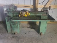
I bought this lathe at an auction today. Everything seemed tight and worth the money to me. It's missing the tool holder and a chuck for the tail stock. I have some questions before I get started.

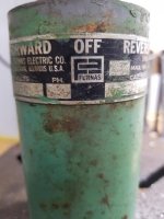
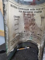
Edit: I do have a good 5 hp 220v motor already but it spins at 3450 rpm. I'm thinking that's too fast.

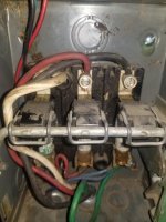
First, it has a 3 phrase, 1 hp motor. The wires were cut so I don't know the condition of the motor and my shop only has 220 single phase. I'm considering getting a 220v single phase 1 hp (maybe more) 1750 rpm motor since I found an owners manual showing how to wire a single phase motor. Is this the best/cheapest solution?

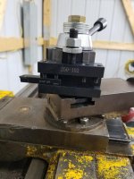
Next question is about the toolholder and tail stock. Am I correct thinking the tail stock is 2MT and the toolholder is AXA?

Thanks for any help. My first plan is to clean up the lathe and then decide how to wire it.

Edit: I forgot to mention I already have a 5 hp 220v single phase motor off an air compressor but it spins 3450 rpm. I'm guessing that's too fast.
 
Last edited:
To avoid these ads, REGISTER NOW!

matt_i

Well-known member
Joined
Mar 14, 2008
Messages
10,729
Location
SE Michigan
Agree you probably want a 1725/1750 rpm motor.

You can go single phase, you can wire up a static phase converter with a start capacitor and a heavy switch or a contactor. That's pretty simple and extremely cheap, less than a VFD or buying a converter. I think you want a 100mfd capacitor per HP of motor you're trying to start. Does the 4914 have a clutched spindle where the motor runs constantly or do you start and stop the lathe by energizing the motor...that latter case is where my plan would go wrong.

I used BXA when I had a 5914 so I'm thinking AXA is a good size for a 4914. One can always space the toolpost higher with a steel block. I lean towards the ability to do detail work with smaller tooling than heavy hogging that the bigger size will allow. Usually there are two sizes which will work.

The manual or accessory list should detail the tailstock, I would say a 2MT is a good guess though.

Edit: looked at some images, does not appear to be a clutched spindle. So the static converter would not work well....however a static plus an idler motor = a rotary phase converter which would work well for the start/stop on the spindle. If you can source a spare 3ph motor of around 1hp you can get into business that way too. The VFD is convenient on the power side but it needs some more detail on the controls side to work properly.
 
Last edited:
OP
M

Mgdoug3

Well-known member
Joined
Mar 2, 2018
Messages
1,391
Location
KY
I should also point out my electrical skills are very limited. Wiring up a single phase motor is much more on my skill level. I can find a 1.5 hp motor for $300 if the footprint is the same.
 

paulsomlo

Well-known member
Joined
Jul 16, 2013
Messages
3,897
Location
Northern Colorado
The lathe originally shipped with a 1hp motor - for $300, if you can verify the 3ph motor on there works, I would buy a VFD, you won't regret it.
 

matt_i

Well-known member
Joined
Mar 14, 2008
Messages
10,729
Location
SE Michigan
If you can extract the 3ph motor, you want to look at its nameplate. Be very careful of the step/cone pulley as that part is going to be very difficult to replace, must be in matched sets for the belt to work correctly...

Match the RPM and the Frame Size for 120 or 240vac operation and you should have one that matches very well. Its likely the 3ph motor was a simple drum switch although the lit below has an option for reversing motor starters and a control transformer setup. But option would likely drive a larger external electrical cabinet.

This document confirms 2MT tailstock and 4MT headstock.
https://www.normanmachinetool.com/w...-Series-Lathe-Specifications-Literature-1.pdf
 
OP
M

Mgdoug3

Well-known member
Joined
Mar 2, 2018
Messages
1,391
Location
KY
Attached is a picture of the 3 phase motor. I got the lathe home today and cleaned it up just a little. I'm waiting on power to the new shop which should happen tomorrow or Tuesday.

I keep going back and forth on what to do. I found a static converter for around $140 (https://www.ajaxtoolsupply.com/phstphcohopo1.html) which I think would work. I'm tempted to try the motor I have laying around but it's a 56 frame and 5/8 shaft and I think the current motor is 7/8.

Does anyone else know of a suitable alternative? I'm not concerned about using VFD and would rather keep it simple.
 

Attachments

  • 20200119_200720.jpg
    20200119_200720.jpg
    61.8 KB · Views: 49

seber

Well-known member
Joined
May 31, 2016
Messages
4,199
Location
Deep East Tx.
Can't tell much from that photo. Can you get a pic of the motor data plate that shows the actual data?
 
OP
M

Mgdoug3

Well-known member
Joined
Mar 2, 2018
Messages
1,391
Location
KY
I wrote down the info on the tag yesterday. I think that's everything that was on the tag.
 

Attachments

  • 20200119_235634.jpg
    20200119_235634.jpg
    48 KB · Views: 34
OP
M

Mgdoug3

Well-known member
Joined
Mar 2, 2018
Messages
1,391
Location
KY
I ended up buying a Phase-a-matic converter box today. I figured it was the cheapest way to make sure the motor was good before I spent any more. I stopped by an older gentleman's place today and that's how he had his 3 phase machine hooked up. I cleaned up the lathe and oil everything. All seems to be working smoothly.

Here's a picture of it. I paid $250 for it and I think I came out alright.
 

Attachments

  • 20200120_171449.jpg
    20200120_171449.jpg
    121.1 KB · Views: 57
OP
M

Mgdoug3

Well-known member
Joined
Mar 2, 2018
Messages
1,391
Location
KY
The phase converter should be in later this week. I attached an picture just making sure I have the wires correct. On the cutoff switch, on each end it's labeled "line" and no label on the middle. Am I correct in assuming it's (T1) (T3) (T2)?
 

Attachments

  • 20200121_101511.jpg
    20200121_101511.jpg
    83.7 KB · Views: 22

bimmer1980

Well-known member
Joined
Feb 5, 2009
Messages
2,104
Location
York, PA
That should be correct......

A couple of things to note.... There should be nine wires coming out of the motor. Depending on if you want to wire it for 220 or 440, different pairs of wires will be tied together. Three of the nine will be your line voltage....i.e. the L1, L2, L3. Generally there is a little wiring diagram on the inside of the cover plate for the motor junction box. I would open this up and just check to be sure. Usually each wire is labeled with a number.

Notice the copper barrels below the switch in your picture. Those appear to be a fuse. The fuse will be sized based on the supplied voltage and therefore the current flow into the motor. Some times instead of a fuse, they use what is called a "heater". This is simply a different type of overload "fuse" that will cause the starter mechanism to trip before it burns up wires or the motor. It is good practice to change the "heater" to the appropriate size if you change voltage.... Sounds complicated, but it is not too bad once you figure it out....

For example. In my Piranha Iron worker with a 10 hp motor, when I put my cord end on for the 240 V 3-phase, I also had to change the set of heaters in the starter box as it was wired for 440 in the previous shop. The current draw is double on 240 compared to the 440.

One more item.... Pending which way the motor turns after you have it wired up... Just swap one of the line wires with another to switch the rotation. For example, if your three incoming wires are Black, Red, Blue for L1, L2, L3 and you want it to go the other direction, just swap Black and Red to L1 and L2 or swap Red and Blue for L2 and L3.

Hopefully this helps....

For $250, I would have bought the lathe as well!!!
 
OP
M

Mgdoug3

Well-known member
Joined
Mar 2, 2018
Messages
1,391
Location
KY
On the motor, I have 4 wires coming out of the wire loom. From memory it's brown, purple, yellow and green. From the drum switch, there's 7 wires. Two of the wires go from the cutoff switch to the drum switch, red and blue.
 
Last edited:

matt_i

Well-known member
Joined
Mar 14, 2008
Messages
10,729
Location
SE Michigan
Did you get PhaseAMatic static or PhaseAMatic rotary?

It does make a difference, the static is just a motor starter...with a static you'd have to interact with the P.A.M. panel each time you want to start the lathe spindle.

With a rotary you only touch the P.A.M. at the start of the work session. THen you control the lathe from the drum switch right there until your work session is over. The rotary can also be setup to run a number of other 3phase machines.

The good news is that if you bought a static you can make it into a rotary by adding one external 3phase "idler motor" that is not hooked to any load.
 
To avoid these ads, REGISTER NOW!
OP
M

Mgdoug3

Well-known member
Joined
Mar 2, 2018
Messages
1,391
Location
KY
I bought just a static converter. I bought it first to make sure the 3 phase motor is working. I thought it would be best to spend as little money as possible at first to make sure everything is working right.
 

matt_i

Well-known member
Joined
Mar 14, 2008
Messages
10,729
Location
SE Michigan
On the motor, I have 4 wires coming out of the wire loom. From memory it's brown, purple, yellow and green. From the drum switch, there's 7 wires. Two of the wires go from the cutoff switch to the drum switch, red and blue.

This would make sense to me if there are 4 (L1, L2, L3, ground) incoming, at the drums switch 8 wires (L1, L2, L3, incoming ground, T1, T2, T3, outgoing ground). Its possible that the ground is not broken in that box or it could be poorly connected just to the housing of the drum switch or the lathe chassis.
 
OP
M

Mgdoug3

Well-known member
Joined
Mar 2, 2018
Messages
1,391
Location
KY
I took the motor plate off and it is wired for low voltage (220 not 440). All wires were black except for the ground but each wire had a metal label clamped on.
 
OP
M

Mgdoug3

Well-known member
Joined
Mar 2, 2018
Messages
1,391
Location
KY
I think I'm going to try the VFD mentioned above since I played around today and couldn't get the magnetic starter to hold down. Reading the Phase-a-matic instructions, tying into T1 and T3 separately should make the magnet switch work.

While looking up pictures of the VFD, I just wire it to the motor and don't use the factory switches. This seems appealing if I have faulty switches. There's only one thing that confuses me. The VFD picture shows U, V, W and ground. How do these wires correlate to T1, T2, and T3? Also, would anyone know how the purple, brown and yellow correspond to T1, T2, and T3?
 
Last edited:

matt_i

Well-known member
Joined
Mar 14, 2008
Messages
10,729
Location
SE Michigan
That is a cheap VFD. Make sure you understand your warranty. If you can live with the button-panel up by the headstock you can make it work. However your OE control lever is not going to be functional unless you do some other wiring to let the drum-switch select the start-stop and the direction of rotation for the motor.

Likely any magnetic devices won't hold in unless the control transformer is powered by (L1, L2)that originates from your residential AC power panel. In other words, L3 in a static system is just a phase-shifted "boost" to get the motor kicked off zero speed. Then the motor runs on 2 of 3 phases in steady-state. So...if your L3 is wired to powering lathe controls there's no current flow there. Solution is to swap any two wires and try again. There are 3 total combinations so 3rd reconfiguration may be in order. Note that swapping any two wires in a 3phase system reverses motor rotation so beware of that with a threaded spindle. You could start the spindle and unscrew the chuck in short order and that's not fun.
 
OP
M

Mgdoug3

Well-known member
Joined
Mar 2, 2018
Messages
1,391
Location
KY
I finally got power to the shop yesterday and hooked L1 and L2 into T1 and T3. I checked voltage and I am getting juice from the plug. The magnet wouldn't hold and I switched wires around with no luck. When I got the machine, wires were cut but still color coded. Trying to find a Furnas 14BA32BC and 8 wire drum switch wire diagram hasn't been easy to come across.
 

matt_i

Well-known member
Joined
Mar 14, 2008
Messages
10,729
Location
SE Michigan
What does the label behind the drum switch read? Something like REV-OFF-FWD?

You should use a meter on continuity with zero volts present to check out the drum switch for connectivity.

It should wire something like this. In OFF position, not shown, all the terminals are isolated.

 
OP
M

Mgdoug3

Well-known member
Joined
Mar 2, 2018
Messages
1,391
Location
KY
I'll take a look when I get back to the shop. I do remember 8 contacts but one wire was a jumper wire.
 
OP
M

Mgdoug3

Well-known member
Joined
Mar 2, 2018
Messages
1,391
Location
KY
I took some pictures of the drum switch. My quick attach toolholder also came in today. I ended up making my own base once I realized a 1.5" 1/4" flat metal would take minimum work to slide in. Drilled out a hole large enough for a nut to be welded in.
 

Attachments

  • 20200123_154503.jpg
    20200123_154503.jpg
    68.3 KB · Views: 11
  • 20200123_154545.jpg
    20200123_154545.jpg
    106 KB · Views: 12
  • 20200123_154607.jpg
    20200123_154607.jpg
    112.5 KB · Views: 8
  • 20200123_154755.jpg
    20200123_154755.jpg
    81.1 KB · Views: 11
OP
M

Mgdoug3

Well-known member
Joined
Mar 2, 2018
Messages
1,391
Location
KY
My Ebay VFD drive came in today. It was really simple to hook up. The lathe works great. I need to build a mount for it but I'm impressed with it and the lathe. It's way better than the Craftsman 109 lathe I got rid of.
 
OP
M

Mgdoug3

Well-known member
Joined
Mar 2, 2018
Messages
1,391
Location
KY
I have another issue I need help on. I have found out that the backing plate isn't 100% straight. With the chuck on, there's about 0.017" of wobble. With the chuck off measuring the spindle theres less than 0.001 of play. The very slight bounce is just from friction of my dial indicator. Do I try a new back plate or can I square up the backing plate in the lathe?

There's no name on the chuck and the flange is 0.405 thick.

Edit: I trued the backing plate and end play on the chuck with the dial indicator is around 0.001". That's probably close enough.
 
Last edited:
OP
M

Mgdoug3

Well-known member
Joined
Mar 2, 2018
Messages
1,391
Location
KY
After I trued the backing plate my attempt at making threads greatly improved. I even made a 1/4" bolt to mount my VFD box today. Here's another attempt making a 3/8-16 bolt. I think I'm really going to like having a lathe around.
 

Attachments

  • 20200126_222244.jpg
    20200126_222244.jpg
    46.8 KB · Views: 6
To avoid these ads, REGISTER NOW!
Top Bottom