To avoid these ads, REGISTER NOW!

CM 1/2 HP motor wiring

ckadams00

Well-known member
Joined
Sep 12, 2011
Messages
1,273
Location
Seattle, WA
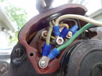
I'm not very educated about wiring . . .working on Dayton 1/2hp capacitor motor and want to run a outlet cord to the motor and then back out to a on off switch.

The motor has four lead posts - one with a "green" wire from the windings and one with a "red" wire from the windings. I assume (I might be wrong) that both of my white wires (switch and plug) connect to one and both my black connect to another.

When I fired it up it spun but blew the breaker. Just want to confirm I am wiring this right .. .

Clockwise: 12 oclock post is the green wire from windings with a brass jumper to 3oclock post which I have both black to.

9 oclock is the post with the red wire from the windings with a brass jumper that I have both white connected to at 6oclock.

I know that the green and red wires are on the right posts.

I have the ground wire from the plug and the switch connected to the ground screw on the motor casing.

What am I doing wrong?:dunno:
 

Attachments

  • DSC02514.jpg
    DSC02514.jpg
    141.7 KB · Views: 13
Last edited:
To avoid these ads, REGISTER NOW!

American Locomotive

Well-known member
Joined
Jan 8, 2017
Messages
11,013
Location
Rhode Island
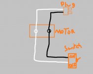
Okay, from what I can tell, you have wired it very wrong. I've made a quick schematic showing how I interpreted you wired it. Can you confirm this is how you wired it?
 

Attachments

  • motor.jpg
    motor.jpg
    38 KB · Views: 8
To avoid these ads, REGISTER NOW!

Bert_

Well-known member
Joined
Dec 24, 2016
Messages
9,775
Location
NW Iowa
The switch should be in series with the black wire coming from the plug. Currently it is wired in parallel which, as you found, makes a short circuit.

I'm not so good with drawings so perhaps some one else can help with that.
 

American Locomotive

Well-known member
Joined
Jan 8, 2017
Messages
11,013
Location
Rhode Island
Yep - what shoud I be doing differently?? And thank you for the help!
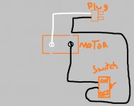
Think about what your circuit is doing. Pretend the motor isn't there, but the connections are made the same way they are now. What happens when you turn the switch on - as in what does the switch effectively do inside? The switch more or less touches two wires together inside. So say you have your cord plugged into the wall - what happens if you were to just touch the two wires on the cord together? You'd be shorting it out. That's what your switch is doing the way it's weird.

Your switch needs to disconnect the power going to the motor, not be put across the power. I've attached a diagram of how it should be wired. But I don't want you to just look at the picture. I want you to understand why it's that way, because this is very important, very basic electrical theory.
 

Attachments

  • motor2.jpg
    motor2.jpg
    44.2 KB · Views: 6
OP
C

ckadams00

Well-known member
Joined
Sep 12, 2011
Messages
1,273
Location
Seattle, WA
Think about what your circuit is doing. Pretend the motor isn't there, but the connections are made the same way they are now. What happens when you turn the switch on - as in what does the switch effectively do inside? The switch more or less touches two wires together inside. So say you have your cord plugged into the wall - what happens if you were to just touch the two wires on the cord together? You'd be shorting it out. That's what your switch is doing the way it's weird.

Your switch needs to disconnect the power going to the motor, not be put across the power. I've attached a diagram of how it should be wired. But I don't want you to just look at the picture. I want you to understand why it's that way, because this is very important, very basic electrical theory.

THANK YOU! This makes a lot of sense.:beer:
 
To avoid these ads, REGISTER NOW!
Top Bottom