To avoid these ads, REGISTER NOW!

Compressor centerfrical switch rpms to low

donjuan

Member
Joined
Feb 21, 2011
Messages
7
Location
RI
Please help
I have a Leeson 1 phase 1740 Rpm 1.5HP motor on my air compressor, when it’s under load the centrifugal switch won’t kick in ? When i disconnect the belt on
The compressor it runs fine. I have replaces the both run and start capacitors.

It seams like it needs more power ? The motor is rated for 115V and
208-230V. I’m thinking it’s wired for 220V??? :headscrat
 

Attachments

  • 83A27766-A9B6-4938-AD2E-6A262D81156E.jpg
    83A27766-A9B6-4938-AD2E-6A262D81156E.jpg
    131.3 KB · Views: 44
  • 8D3E30E4-59D3-4F93-AC1C-F555C1A5ABDE.jpg
    8D3E30E4-59D3-4F93-AC1C-F555C1A5ABDE.jpg
    73.6 KB · Views: 29
  • 79A83E6A-5F0A-42FD-8F06-F25D0BEF862C.jpg
    79A83E6A-5F0A-42FD-8F06-F25D0BEF862C.jpg
    77.4 KB · Views: 36
  • CCA2595E-42D3-4085-B0C9-D32E4155660C.jpg
    CCA2595E-42D3-4085-B0C9-D32E4155660C.jpg
    110.4 KB · Views: 34
  • 36235731-CC31-4138-B077-1F55D92090F4.jpg
    36235731-CC31-4138-B077-1F55D92090F4.jpg
    107.7 KB · Views: 31
To avoid these ads, REGISTER NOW!

The Cobbler

Super Moderator
Staff member
Joined
Oct 24, 2013
Messages
26,244
Location
Niagara Region, Ontario, Canada
has it ever run properly while in your possession?
if there is no air in the tank does it start up?
does the compressor turn over easily by hand?
have you looked at the wiring in the motor to determine the voltage it is wired for?
 
OP
D

donjuan

Member
Joined
Feb 21, 2011
Messages
7
Location
RI
1. I don’t know if it ever ran correct ? I bought it from an estate but when I plugged it in it ran but I never totally filled the tank.
2 yes it starts fine but it never comes off the start capacitor with the compressor hooked up
It will fill to about 20psi then starts to die! I can manually turn it to the run capacitor but
It just dies
3. The compressor is fine
4 I’m not sure on the wiring because of the capacitors
5 with no load the centrifugal switch works fine?

I tried to post a video but it won’t upload
Thanks
 

dogdog

Well-known member
Joined
Nov 15, 2011
Messages
12,711
I think your problem is some where else....
The centrifugal switch supposedly disconnects the start coil once the motor is up to speed.
Maybe your compressor is seizing up or incorrect pulley installed, or 1HP is just not the right motor for that compressor ?
 

American Locomotive

Well-known member
Joined
Jan 8, 2017
Messages
11,160
Location
Rhode Island
1.5HP is a lot of power for a normal 120 outlet, and it won't take much for that motor to have issues with power.

It sounds to me like the motor is wired for 240v though. Post a picture of the wiring diagram, and the connections it has.
 
OP
D

donjuan

Member
Joined
Feb 21, 2011
Messages
7
Location
RI
Ok
The motor looks to be original to the compressor

The voltage is normal 110V on a12 gauge wire circuit

I can manually kick the centrifugal switch from the start to the run capacitor and the motor
Doesn’t have the torque to keep running and stops.

I’m not running an extension cord just 12 gauge wire about 3 ft long to a socket

I don’t have a wiring diagram for the compressor but I’ll see if I can make one up this week

Thanks
 

larry_g

Well-known member
Joined
Apr 28, 2007
Messages
16,932
Location
oregon
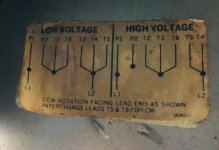
In your first picture of the motor data plate there is a diagram showing the wiring for both high and low voltage. Look inside the motor and confirm which way it is wired. Confirm which wires are connected together. This should be your first step.

lg
no neat sig line
 
Last edited:
To avoid these ads, REGISTER NOW!
OP
D

donjuan

Member
Joined
Feb 21, 2011
Messages
7
Location
RI
Oooooo! :bowdown:
Ok, this is what I need to know but please teach how to read
The wires. It shows the wires going to “line” and “tape” ?:headscrat
What does that mean ???
Thanks for the help
 

Attachments

  • DD6F347E-F0FE-4AE6-B50A-2CDF13B22E9A.jpg
    DD6F347E-F0FE-4AE6-B50A-2CDF13B22E9A.jpg
    100.7 KB · Views: 38

OccupantRJ

Well-known member
Joined
May 15, 2009
Messages
11,542
Location
Eastern North Carolina
On the diagram, the line wires are your incoming power. The wires that are marked as tape get attached together as a group. This groups the wires for the different required voltages. I normally use wire nuts, then tape them to the wires afterward for a bit of assurance from vibrating loose. There are stretchy splicing tapes, but something like 3m 33 electrical tape will work for you. Some motors will have ring terminals attached to the individual wires, and these get bolted together, then taped for insulating them. For that, use splicing tape which is stretched on as it is applied.
 
Last edited:

larry_g

Well-known member
Joined
Apr 28, 2007
Messages
16,932
Location
oregon
Quick check is look at your two line (power) wires going into the motor. If one is connected to 3 wires then it is set for 115v. If one of the line wires connects to 2 wires then your set for 208-230v. From there you can figure out what you need to change if anything.

lg
no neat sig line
 
OP
D

donjuan

Member
Joined
Feb 21, 2011
Messages
7
Location
RI
5F5015CF-19BF-44C4-9AC4-FDA34790DAE3.jpg

B80E8527-CC86-435E-921E-2CA82B5967D7.jpg

Ok!
It looks like the motor is wired for 220v clock wise rotation ! :lol_hitti

Should I keep it at 220 or 110 ?

Also sending power to L1 & L2 are hot wires and a neutral wire can I just use aground wire ? :shocking:
Thanks for the help guys
 

Cruzan80

Well-known member
Joined
Jul 22, 2015
Messages
4,493
Location
Denver, CO
Depends on if you have a 220 outlet or not. If not, leaving it in 220 configuration but supplying 110 won't work.

Don't use a ground wire for L1/L2. In 110, one is hot, one is neutral. In 220, both are hot. Both 110 and 220 should have a ground to the frame of the motor.
 
OP
D

donjuan

Member
Joined
Feb 21, 2011
Messages
7
Location
RI
Ok,
I have more questions than answers
1 i hooked 220 to L1 and L2 and grounded the motor
Nothing! :headscrat
2 next I rewired the motor for 110v and switched
L1 hot, L2 neutral then Voilà it runs great! I adjusted
The switch to shut off at 140 & on at 90 psi :thumbup:
3. O wait don’t get that excited because Now at 90 psi
When the motor tries to start its drawing to many amps
And trips the breaker (20 amp on 12 wire)
4. I turned the cut in pressure down to 80 psi
And it works great 👍
Question?
1. Why won’t it run on 220v ?
2. Seams like 20amp circuit would be fine but
Should it be 30?
Thanks for all the help this is my first time really digging into an electric ⚡
Motor. We always had an electrician that made everything sound like he
Was the only one that knew anything! :rant:
 

OccupantRJ

Well-known member
Joined
May 15, 2009
Messages
11,542
Location
Eastern North Carolina
When the compressor shuts down, it must somehow bleed air off the head or output tube to allow a restart with no pressure to overcome. Do you hear a release of air upon shutdown?
A 1-1/2 hp motor should run on a 20 amp circuit. Has someone put a larger pulley on the motor? This could bog it down. On the 240 volt hookup, maybe you missed something in the wiring diagram. Take a pic of the unit up close and post it.
 

wyliesdiesels

Well-known member
Joined
Aug 14, 2012
Messages
20,256
Location
Modesto, CA
5F5015CF-19BF-44C4-9AC4-FDA34790DAE3.jpg

B80E8527-CC86-435E-921E-2CA82B5967D7.jpg

Ok!
It looks like the motor is wired for 220v clock wise rotation ! :lol_hitti

Should I keep it at 220 or 110 ?

Also sending power to L1 & L2 are hot wires and a neutral wire can I just use aground wire ? :shocking:
Thanks for the help guys

Im assuming you meant use the neutral as ground.

A neutral should never be used as an EGC.

Is this motor connected to the main service panel?

Ok,
I have more questions than answers
1 i hooked 220 to L1 and L2 and grounded the motor
Nothing! :headscrat
2 next I rewired the motor for 110v and switched
L1 hot, L2 neutral then Voilà it runs great! I adjusted
The switch to shut off at 140 & on at 90 psi :thumbup:
3. O wait don’t get that excited because Now at 90 psi
When the motor tries to start its drawing to many amps
And trips the breaker (20 amp on 12 wire)

4. I turned the cut in pressure down to 80 psi
And it works great ��
Question?
1. Why won’t it run on 220v ?
2. Seams like 20amp circuit would be fine but
Should it be 30?

Thanks for all the help this is my first time really digging into an electric ⚡
Motor. We always had an electrician that made everything sound like he
Was the only one that knew anything! :rant:

#3) That makes sense that its drawing too much current for a 20a 120v circuit. The FLC for 1.5HP 120v is 20a and the nameplate FLA on your motor is 17.2a. As the load gets harder on the motor it will draw more power.

NEC requires 25a(#12 THHN or #10 NM) rated wire and breaker can be 250% max so 50a to prevent nuisance trips. So if you want to keep it on 120v circuit, you will need a larger circuit. I would get it working on 240v.

Q1) Not sure without seeing how you hooked up the leads. Perhaps it wasnt wired correctly. Check your motor leads again.

Q2 20a isnt large enough for 120v operation but if you run it on 240v, 20a circuit should have no problem.

here is the NEC FLC chart:
430-248.png
 
Last edited:
To avoid these ads, REGISTER NOW!
Top Bottom