To avoid these ads, REGISTER NOW!

Compressor not kicking on - issue with starter box

buening

Well-known member
Joined
Dec 17, 2007
Messages
1,338
Location
Decatur, IL
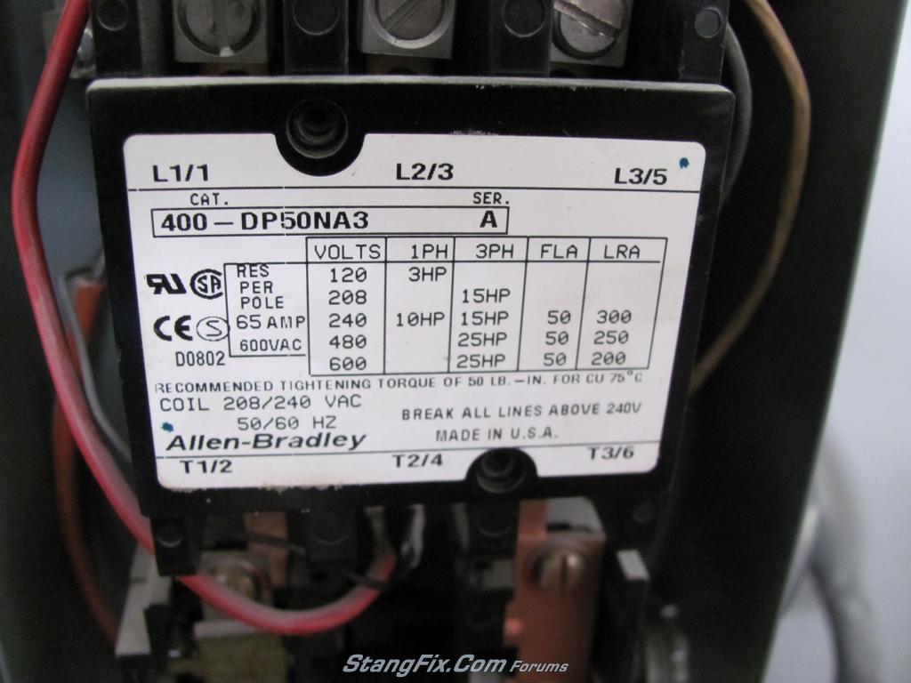
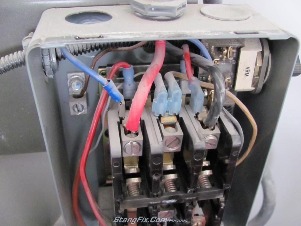
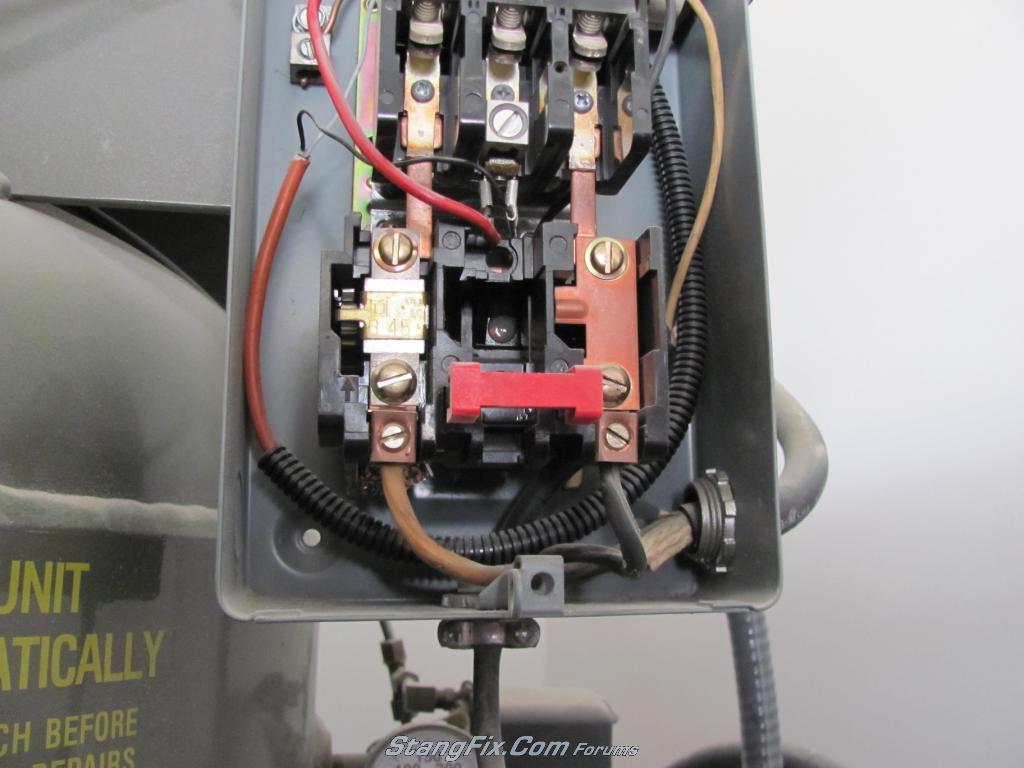
I have a 7.5hp ph1 air compressor with a NEMA 1 starter box. It is the IMC Bel Aire 318VL 80gal. Attached is a PDF of the wiring diagram to help with everything. I've verified 120v to each L1 and L2 leg coming in. All of the safety circuit are closed and have 120v going through them (auxiliary contactor is the center contactor that would be used on a 3ph motor). I also have 120v at the two connections of the coil C1 and C2. The issue is the contacts aren't closing in order to send power to the motor. I apologize for my lack of magnetic starter intelligence, but does this mean the coil is bad? I'm not sure how the internals work to cause the contacts to close. I popped the plastic cover off over the contacts and pressed the bar in a couple times to make sure it didn't get stuck, and it was fine. Turned power back on, and still no worky. :(

I bought the compressor used and it had a blown coil. I put a new coil in and its been working great for about 3 years or so. It does sound like a whip is cracking when the compressor kicks off, which from what I'm told is normal for a magnetic starter with this size motor. I think it is the electricity arcing the contacts as they open.
 

Attachments

  • Low Oil Wiring.pdf
    23 KB · Views: 33
To avoid these ads, REGISTER NOW!

930dreamer

Super Moderator
Staff member
Joined
Oct 7, 2009
Messages
22,942
Location
Amarillo,TX and Stinnett,TX
1. Does the starter have heaters(metal springs that burn when the amps are exceeded).
2. Have you tried to close the contact with a piece of wood with the power on?
 

Attachments

  • d_8478.jpg
    d_8478.jpg
    48.9 KB · Views: 2
  • d_5416.jpg
    d_5416.jpg
    30.9 KB · Views: 1
Last edited:

Zrexxer

Well-known member
Joined
Jan 23, 2007
Messages
5,058
Location
Pflugerville, TX
You say you have 120V at the coil but coils come in different voltage configurations. Is that a 240V coil by chance?
 
OP
B

buening

Well-known member
Joined
Dec 17, 2007
Messages
1,338
Location
Decatur, IL
1. Does the starter have heaters(metal springs that burn when the amps are exceeded).
2. Have you tried to close the contact with a piece of wood with the power on?

The one on the left has a clip or something and looks similar to this:

SB_FULL.jpg


The one on the right is a solid strip without the clip/spring piece.

I have not tried to manually close the contacts with the power on. Should I?
 

Zrexxer

Well-known member
Joined
Jan 23, 2007
Messages
5,058
Location
Pflugerville, TX
The one on the left has a clip or something and looks similar to this:

The one on the right is a solid strip without the clip/spring piece.
That's your thermal overload device, sometimes called a "heater." On single phase there's just one used, the other leg has a solid copper buss.
 
Last edited:
OP
B

buening

Well-known member
Joined
Dec 17, 2007
Messages
1,338
Location
Decatur, IL
You say you have 120V at the coil but coils come in different voltage configurations. Is that a 240V coil by chance?

It is a 240v coil. The Contactor/coil assembly is an Allen-Bradley 400-DP50NA3 and was purchased new in Dec 2007.

As per the diagram, the L1 of the incoming feed provides 120v to the C1 coil leg (once it makes it through the pressure switch and low oil switch). The L2 of the incoming feed provides the other 120v to the C2 leg of the coil. The "X" and "Y" in the diagram is the Overload Relay block. I'm assuming that the two posts of the coil with each having 120v constitutes a 240v coil?

I will snap a pic of the starter when I go home for lunch today.
 
Last edited:
OP
B

buening

Well-known member
Joined
Dec 17, 2007
Messages
1,338
Location
Decatur, IL
That's your thermal overload device, sometimes called a "heater." On single phase there's just one used, the other leg has a solid copper buss.

Correct, the left is a heater and the right is what I've heard as called a "jumper"
 
To avoid these ads, REGISTER NOW!

OccupantRJ

Well-known member
Joined
May 15, 2009
Messages
10,966
Location
Eastern North Carolina
With power off, disconnect at least one wire to the coil and check for resistance through the coil in ohms with a volt-ohmeter, or get the coil checked after removing it and have someone check it for you. With 240 volts at the coil terminals, this is a likely coil failure, but get it checked to verify. This is a common problem with contactors and motor starters. My guess is that the coil has an inner open connection, or in other words, no continuity.
 
Last edited:
OP
B

buening

Well-known member
Joined
Dec 17, 2007
Messages
1,338
Location
Decatur, IL
Picture of the contactor cover:

231-140311115036-76701683.jpeg


Overall:

231-140311115042-767796.jpeg


Zoomed in upper

231-140311115047-767816.jpeg


Zoomed in lower:

231-140311115053-76791543.jpeg


Tan and black wire is from the pressure switch, and the small gauge black and white wires from the convoluted tubing is from the low oil level switch (LOLS). The wiring diagram shows an auxiliary contactor, but the L2/T2 was used instead since an Allen Bradley contactor was used instead of the Square D one.

How its wired up: Blue wire from L1 goes to the On/Off switch in upper right corner of pic. From switch, black wire goes to pressure switch and back through tan wire to the center L post (L2 if you go by the cover), from that shared post it goes through white wire to the LOLS and then back to the bottom center post (T2 from the cover), then from that shared post the red wire goes to C1 of the coil.

For the other leg of the coil, there is a direct wire from the L3 post to the C2 post of the coil. It appears the Overload Relay block was bypassed when I wired it, and can't recall the reason I was told this. Maybe due to already having a heater?

Hope this clarifies what I have and if you can, let me know what you think the issue is. I have 120V at posts L1, L2, L3, T2, C1, and C2. From what I know, this means that everything is working up to the coil (no broken circuits).
 

Attachments

  • IMG_1691a.jpg
    IMG_1691a.jpg
    132.1 KB · Views: 7
  • IMG_1692a.jpg
    IMG_1692a.jpg
    135.4 KB · Views: 3
  • IMG_1693a.jpg
    IMG_1693a.jpg
    130.4 KB · Views: 2
  • IMG_1694a.jpg
    IMG_1694a.jpg
    135.2 KB · Views: 2
OP
B

buening

Well-known member
Joined
Dec 17, 2007
Messages
1,338
Location
Decatur, IL
With power off, disconnect at least one wire to the coil and check for resistance through the coil in ohms with a volt-ohmeter, or get the coil checked after removing it and have someone check it for you. With 240 volts at the coil terminals, this is a likely coil failure, but get it checked to verify. This is a common problem with contactors and motor starters.

Any idea what kind of resistance I should be expecting?
 

Aceman

Well-known member
Joined
Jan 28, 2007
Messages
2,513
Location
Eastern Oregon
Don't measure hot to ground, knowing there's 120v means nothing. Something can backfeed throwing your readings off. Don't worry about ohming anything at this point.

1. Turn on power. Verify you have 240v at the top of your starter on the two incoming legs(black and red). Turn your selector switch on(is it a 3 pos. hand/off/auto or just on/off?). Make sure it's either in auto or on, verify the pressure switch contacts are closed. Now put your meter leads on the coil. You may have to shut power off temporarily to slide those insulated female spade connectors back off the coil a little bit to be able to test, I can't see any part of the metal connection showing to put your meter leads on.

If you read 240v on the coil and the contactor isn't pulling in, your coil is shot. If you don't read 240v, you'll need to trace backwards until you find where you lost continuity, whether it's the selector switch, oil switch, pressure switch, overloads, bad connection, whatever. When your checking for continuity through your devices remove the wire from one side. You don't want anything backfeeding fouling up your readings.
 
OP
B

buening

Well-known member
Joined
Dec 17, 2007
Messages
1,338
Location
Decatur, IL
Don't measure hot to ground, knowing there's 120v means nothing. Something can backfeed throwing your readings off. Don't worry about ohming anything at this point.

1. Turn on power. Verify you have 240v at the top of your starter on the two incoming legs(black and red). Turn your selector switch on(is it a 3 pos. hand/off/auto or just on/off?). Make sure it's either in auto or on, verify the pressure switch contacts are closed. Now put your meter leads on the coil. You may have to shut power off temporarily to slide those insulated female spade connectors back off the coil a little bit to be able to test, I can't see any part of the metal connection showing to put your meter leads on.

If you read 240v on the coil and the contactor isn't pulling in, your coil is shot. If you don't read 240v, you'll need to trace backwards until you find where you lost continuity, whether it's the selector switch, oil switch, pressure switch, overloads, bad connection, whatever. When your checking for continuity through your devices remove the wire from one side. You don't want anything backfeeding fouling up your readings.

Thanks for the help! Verified everything and by unplugging one connector at a time I was able to verify that the low oil level switch was the culprit. Learned something new today and thanks everyone for the help! I never even thought about it backfeeding through the system.
 
To avoid these ads, REGISTER NOW!
Top Bottom