Hi,
My new compressor just arrived and I'm trying to plan a good aftercooler and water separator system for it. The main use will be plasma cutting.
This is my first big compressor and I'm trying to figure out how all the parts work, especially around the check valve(s) and unloader valve.
It is a Quincy Q13160VQ:
http://www.aircompressorsdirect.com/Quincy-Q13160VQ-Air-Compressor/p12330.html
I ordered an automotive transmission oil cooler to use as an aftercooler, but the inlets are quite a bit smaller than the 1/2" NPT outlet on the tank (maybe 5/16"), so I'm hesitant to use it in case it restricts airflow too much. Are there any other options like this that have 1/2" fittings and don't cost >$300?
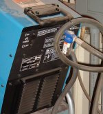
Here's a picture showing the main plumbing from the pump to the receiver:

Here's the bottom end of the big copper tube going into the receiver:

From what I read, I believe the check valve as located inside the tank under that assembly and the skinny tube going off to the side is used to unload pressure from the pump once it shuts off.
I'd like to keep pressure in whatever aftercooler system I go with so the pump doesn't have to work to refill it every time, especially if I go the black pipe route since it will take a long time to fill/drain all that air space vs. just the normal hissing you get at the end of a cycle unloading the pump.
Would I need to add another check valve between the pump and aftercooler and put the unloader line between the pump and the new check valve in order to keep the aftercooler lines pressurized?
I'm thinking it would go like this:
pump > T-fitting feeding:
1. unloader line going to pressure switch
2. check valve > aftercooler > existing check valve entry to receiver with the old unloader line clamped off.
Does that make sense or is there a better way to do this?
Also, what's the little tower with the red circle on top? It looks like it has a small hole drilled near the top.
Thanks!
Jacob
My new compressor just arrived and I'm trying to plan a good aftercooler and water separator system for it. The main use will be plasma cutting.
This is my first big compressor and I'm trying to figure out how all the parts work, especially around the check valve(s) and unloader valve.
It is a Quincy Q13160VQ:
http://www.aircompressorsdirect.com/Quincy-Q13160VQ-Air-Compressor/p12330.html
I ordered an automotive transmission oil cooler to use as an aftercooler, but the inlets are quite a bit smaller than the 1/2" NPT outlet on the tank (maybe 5/16"), so I'm hesitant to use it in case it restricts airflow too much. Are there any other options like this that have 1/2" fittings and don't cost >$300?
Here's a picture showing the main plumbing from the pump to the receiver:
Here's the bottom end of the big copper tube going into the receiver:
From what I read, I believe the check valve as located inside the tank under that assembly and the skinny tube going off to the side is used to unload pressure from the pump once it shuts off.
I'd like to keep pressure in whatever aftercooler system I go with so the pump doesn't have to work to refill it every time, especially if I go the black pipe route since it will take a long time to fill/drain all that air space vs. just the normal hissing you get at the end of a cycle unloading the pump.
Would I need to add another check valve between the pump and aftercooler and put the unloader line between the pump and the new check valve in order to keep the aftercooler lines pressurized?
I'm thinking it would go like this:
pump > T-fitting feeding:
1. unloader line going to pressure switch
2. check valve > aftercooler > existing check valve entry to receiver with the old unloader line clamped off.
Does that make sense or is there a better way to do this?
Also, what's the little tower with the red circle on top? It looks like it has a small hole drilled near the top.
Thanks!
Jacob