burgie
Well-known member
Good evening...
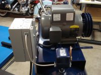
Well, the new 5 HP Baldor motor is wired and running...but not without some electrical modifications...
So first, a little background: The original 5 HP 3-phase motor that was OEM on the compressor was wired in series with the pressure switch. This meant that the full current load of the motor was carried through the switch contacts. This was acceptable for a lower current 3-phase motor because the switch was rated for a 5 HP, 3-phase motor. However, if used in a 1-phase application it was only rated for a maximum of 3 HP.
I did not want to have to purchase a new pressure switch. The original one worked fine, whenever restoring something I like to maintain originality and besides, it looks cool all cleaned and painted to match the tank!!!
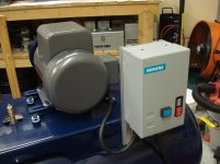
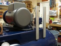
I purchased a Siemens WS5-2301P Magnetic Starter and accessory Siemens-Furnas Push Button Kit 49SBPB5. My goal was to use BOTH the start/stop switch AND the pressure switch to control the starter relay, thus negating the need for a replacement pressure switch capable of handling a higher current serial load and separate high amperage switch.
To accomplish this, I first purchased an auxiliary relay from Automation Direct. It is a 240V DPDT relay and the relay and mounting base cost about $12 and arrived about 2 days after I ordered it on the vendor web site.
When viewing the schematic, L2 voltage feeds one side of the starter relay coil and also one side of the aux relay coil. L1 voltage goes through the heater/normally closed (NC) contact, feeds the STOP pushbutton, which is also normally closed and sits on Pin 5 (wiper) of the relay. When the START pushbutton is depressed, L1 voltage is applied momentarily to the other side of the aux relay coil (Pin 7) which energizes the coil and makes a Pin 5 – Pin 3 contact. This latches the relay so even when the momentary START pushbutton is released the relay stays energized. L1 voltage then goes through the NC pressure switch to the other starter relay coil, thus energizing the coil which, in turn passed the high current 230V to the motor.
Now, once pressure is reached in the tank, the NC pressure switch open and shuts the motor off. Or, depressing the STOP pushbutton removes the voltage at the Pin 5 wiper thus de-energizing the starter relay which, in turn, shuts the motor off.
I hope this explains things properly? It is installed on my compressor and the motor starts and stops whenever I depress the respective pushbutton and, even though the pump isn’t done, I manually activated the pressure switch and it, too, starts and stops the motor.
I searched the web extensively for instructions on how to wire the starter and accessory switch kit and found very little information and wanted to share this with the hopes that others will find it useful.
Have a great evening folks…
Burgie
Well, the new 5 HP Baldor motor is wired and running...but not without some electrical modifications...
So first, a little background: The original 5 HP 3-phase motor that was OEM on the compressor was wired in series with the pressure switch. This meant that the full current load of the motor was carried through the switch contacts. This was acceptable for a lower current 3-phase motor because the switch was rated for a 5 HP, 3-phase motor. However, if used in a 1-phase application it was only rated for a maximum of 3 HP.
I did not want to have to purchase a new pressure switch. The original one worked fine, whenever restoring something I like to maintain originality and besides, it looks cool all cleaned and painted to match the tank!!!
I purchased a Siemens WS5-2301P Magnetic Starter and accessory Siemens-Furnas Push Button Kit 49SBPB5. My goal was to use BOTH the start/stop switch AND the pressure switch to control the starter relay, thus negating the need for a replacement pressure switch capable of handling a higher current serial load and separate high amperage switch.
To accomplish this, I first purchased an auxiliary relay from Automation Direct. It is a 240V DPDT relay and the relay and mounting base cost about $12 and arrived about 2 days after I ordered it on the vendor web site.
When viewing the schematic, L2 voltage feeds one side of the starter relay coil and also one side of the aux relay coil. L1 voltage goes through the heater/normally closed (NC) contact, feeds the STOP pushbutton, which is also normally closed and sits on Pin 5 (wiper) of the relay. When the START pushbutton is depressed, L1 voltage is applied momentarily to the other side of the aux relay coil (Pin 7) which energizes the coil and makes a Pin 5 – Pin 3 contact. This latches the relay so even when the momentary START pushbutton is released the relay stays energized. L1 voltage then goes through the NC pressure switch to the other starter relay coil, thus energizing the coil which, in turn passed the high current 230V to the motor.
Now, once pressure is reached in the tank, the NC pressure switch open and shuts the motor off. Or, depressing the STOP pushbutton removes the voltage at the Pin 5 wiper thus de-energizing the starter relay which, in turn, shuts the motor off.
I hope this explains things properly? It is installed on my compressor and the motor starts and stops whenever I depress the respective pushbutton and, even though the pump isn’t done, I manually activated the pressure switch and it, too, starts and stops the motor.
I searched the web extensively for instructions on how to wire the starter and accessory switch kit and found very little information and wanted to share this with the hopes that others will find it useful.
Have a great evening folks…
Burgie