
You are using an out of date browser. It may not display this or other websites correctly.
You should upgrade or use an alternative browser.
You should upgrade or use an alternative browser.
Compressor Restoration-Final Assembly
- Thread starter burgie
- Start date
Chandos
Well-known member
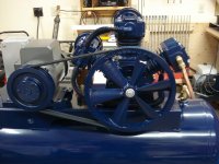
Cylinder-to-cylinder air delivery lines installed...
Did you fabricate the air lines or are they original? If you replaced them, can you provide a source? I've got a Champion R-15 two stage of about the same vintage and cooling fins on mine are a bit battered.
Beautiful job on this rebuild!
Chandos
Miles...
My literaure from Curtis shows 17.4 SCFM @ 175 psi. The flywheel is 16" and the motor sheave is 8.5". The motor is a real 5HP Baldor (Frame 184, 1.125" arbor shaft, 21FLA, 1740 rpm) so when operating the pump is churning at approximately 923 rpm...
Chandos...
The inter-cylinder air lines are original...
Thanks for the kind words. I really enjoy these restoration projects. They take time because my money tree out back is usually bare...but I get things when I can afford them and get the projects done...
My next is a Saylor Beall 80 gallon vertical with a Model 703 2-stage pump!!!
OK...so this morning I went to the compressor store and they bent me a piece of copper to connect the high pressure output to the tank input...
From completely empty to full 175 psi in 10 minutes. I made a slight adjustment to the pressure switch as it was set for 155 psi and I wanted it set for 175 psi. After bleeding pressure it kicked on at 145 psi and took 88 seconds to charge back to 175 psi...
Later I'll be adding a cooler between the output and the tank, similar to the one built by Alan Camby, but for now it'll make air and re-charge my fun money account...a.k.a. wallet!!!
Here is a video showing the compressor running till it kicks off at 175 psi...
Attachments


RickP330
Well-known member
That looks awesome dude!!!
RP
RP
Way to go on the rebuild.
SCscoutguy
Well-known member
Are you going to fabricate a cage to go around the drive belt/fan?
JASTECH
Well-known member
(wiping drool)
bsaint
Well-known member
Are you going to fabricate a cage to go around the drive belt/fan?

Ben Buck
Well-known member
 Oh Bob, you have done quite well on the rebuild. The U tube video is great, sounds good running! Great work all around!! I'm looking forward to the 80 gal rebuild you have planned. ( oh , I did find that 10 mm x 1.50 adapter I needed to add a drain on my 80 gal unit, from a place in Indiana, it will be here tomorrow!)
Thanks folks...
Yea...the 80-gallon Saylor Beall will be another fun project!! The motor works awesome and, aside from a new mag starter and an overhaul kit from Saylor Beall...most of that is elbow grease and sweat equity...so that should go much faster than this one...
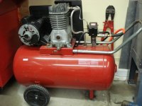
I still have the shroud and Alan Camby cooler to do but, again, at least I can use the compressor now and give my trusted and reliable 26 year old Craftsman (that I bought brand new) a well-deserved rest. That little compressor has served me well for years and still runs strong!!!
Yea...the 80-gallon Saylor Beall will be another fun project!! The motor works awesome and, aside from a new mag starter and an overhaul kit from Saylor Beall...most of that is elbow grease and sweat equity...so that should go much faster than this one...
I still have the shroud and Alan Camby cooler to do but, again, at least I can use the compressor now and give my trusted and reliable 26 year old Craftsman (that I bought brand new) a well-deserved rest. That little compressor has served me well for years and still runs strong!!!
Attachments
Miles...
My literaure from Curtis shows 17.4 SCFM @ 175 psi. The flywheel is 16" and the motor sheave is 8.5". The motor is a real 5HP Baldor (Frame 184, 1.125" arbor shaft, 21FLA, 1740 rpm) so when operating the pump is churning at approximately 923 rpm...
That's one hell of a compressor! Very nice work!
I dont even want to discuss my compressor...
alan camby
Well-known member
Lookin good
Enjoying watching it all come together. Never been in a compressor pump.
Worked on the reed/heads a few times.
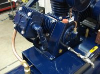
Thought it was interesting that the low pressure rod design is different then the high pressure. Noticed that the HP has needle roller bearings while the LP has a brass bushings on the piston pins. Makes since that they are in that order.
Like the 2000psi ball valve oil drain, hope it can handle the pressure . Assuming that the bolt is to guard from accidental opening. I agree on your BV size. I have a 1/4" locking BV and it takes a good while for all the fluid to drain. If i extend mine i am going to change over to 3/8". Mine has a 1/4"npt port on the pump but would still like to go larger. Guess changing mine would be a waste of money at this point since I only drain once a year. Put a bucket under it and come back in a few hours.

Look forward to the cooler install. I can't take the credit for the idea or design. All my designs came from studying everyone else's here on GJ and modifying to my taste.
Here is a link to my photobucket photos. Don't think they all made it into the threads. Love the pressure switch, "Not made in China" sticker.
I also have some of my other project picture folders here.
http://s1206.beta.photobucket.com/u...ressor?&_suid=1355975790911046370303231047854
Enjoying watching it all come together. Never been in a compressor pump.
Worked on the reed/heads a few times.
Thought it was interesting that the low pressure rod design is different then the high pressure. Noticed that the HP has needle roller bearings while the LP has a brass bushings on the piston pins. Makes since that they are in that order.
Like the 2000psi ball valve oil drain, hope it can handle the pressure
. Assuming that the bolt is to guard from accidental opening. I agree on your BV size. I have a 1/4" locking BV and it takes a good while for all the fluid to drain. If i extend mine i am going to change over to 3/8". Mine has a 1/4"npt port on the pump but would still like to go larger. Guess changing mine would be a waste of money at this point since I only drain once a year. Put a bucket under it and come back in a few hours.
Look forward to the cooler install. I can't take the credit for the idea or design. All my designs came from studying everyone else's here on GJ and modifying to my taste.
Here is a link to my photobucket photos. Don't think they all made it into the threads. Love the pressure switch, "Not made in China" sticker.
I also have some of my other project picture folders here.
http://s1206.beta.photobucket.com/u...ressor?&_suid=1355975790911046370303231047854
Last edited:
Oh yea...the motor sheave and flywheel cover is definitely next...even before the Alan Camby air cooler setup. I am thinking of a way that will be functional as well as cool looking...
I'm thinking an art deco design water jet aluminum sheet. Sheet brass all shined up would be even cooler but $$. That compressor deserves something really cool looking. Fantastic restore!!
Steve
Compressor is Over-The-Top . . . AWESOME!!
What a fabulous machine fully restored . . . plus a work of art. Runs so quiet, I'm curious the estimate of Db level?
I'd vote +1 with Steve V that belt cover needs to be special. Maybe louvered sheet copper with stainless steel surround? Or lattice screen made of stainless steel flatstock welded together with overall surround made of copper?
HoosierBuddy
Well-known member
Wow. Really great job!
I love it.
Phil
I love it.
Phil
Alan...
The original HP rod had a bronze bushing also but the update included a much preferred roller bearing. It will handle the greater pressure much better than the bronze version.
The drain is more than adequate in size and is made of stuff I had collected over the years. The stop is actually a 10-32 pan head screw with a stainless steel tubing sleeve slid over it to hide the threads. I then used a nut to secure the sleeve, applied a little blue loctite to the threads and then threded the assembly into the valve. Your setup is different but served the same purpose...protection against accidental opening!!!
The inverted chrome "L" at the end of the drain is female threaded so when I do change the fluid I'll thread in a barbed connection to hand tight, push on a piece of tygon tubing that will go to a bucket on the floor and then drain it. Once drained, simply remove the barbed assembly and fill it back up (of course...wipe down and polish the chrome snorkel too)
I did notice an upgrade to my electrical system that I am going to fix. I need 220V indicator LEDs that will show when the mag starter is in the ON or OFF position. So a minor upgrade soon...
The original HP rod had a bronze bushing also but the update included a much preferred roller bearing. It will handle the greater pressure much better than the bronze version.
The drain is more than adequate in size and is made of stuff I had collected over the years. The stop is actually a 10-32 pan head screw with a stainless steel tubing sleeve slid over it to hide the threads. I then used a nut to secure the sleeve, applied a little blue loctite to the threads and then threded the assembly into the valve. Your setup is different but served the same purpose...protection against accidental opening!!!
The inverted chrome "L" at the end of the drain is female threaded so when I do change the fluid I'll thread in a barbed connection to hand tight, push on a piece of tygon tubing that will go to a bucket on the floor and then drain it. Once drained, simply remove the barbed assembly and fill it back up (of course...wipe down and polish the chrome snorkel too
)I did notice an upgrade to my electrical system that I am going to fix. I need 220V indicator LEDs that will show when the mag starter is in the ON or OFF position. So a minor upgrade soon...
alan camby
Well-known member
I bought my 220 volt leds through mcmaster-carr.
I can get you a part # if interested.
I can get you a part # if interested.
BTW...I followed the idea by KO and sent FS Curtis an e-mail (with a few pics and the YouTube URL showing it ruinning) and asked for a couple FS Custis decals to put on the tank.
I am awaiting their response. I'll let ya know if they are gonna send me a couple freebies!!!
I am awaiting their response. I'll let ya know if they are gonna send me a couple freebies!!!
alan camby
Well-known member
Part # 7380k5
Several colors to choose from. Think mine are green.
They are decent quality, all plastic. I am happy with mine
Edit: i had the part # wrong, changed it. Silly smartphone.
Edit: Back home and on the laptop. Here is a link to the page.
http://www.mcmaster.com/#panel-mount-led-lights/=kodwis
Several colors to choose from. Think mine are green.
They are decent quality, all plastic. I am happy with mine
Edit: i had the part # wrong, changed it. Silly smartphone.
Edit: Back home and on the laptop. Here is a link to the page.
http://www.mcmaster.com/#panel-mount-led-lights/=kodwis
Last edited:
RickP330
Well-known member
Thought it was interesting that the low pressure rod design is different then the high pressure. Noticed that the HP has needle roller bearings while the LP has a brass bushings on the piston pins. Makes since that they are in that order.
What an awesome thread. This is why I love GJ ;-)
Nice catch on the needle bearing Alan. I had to go back and take a double look at it. Just curious, since it is an upgrade I can see that it covers the oil hole which used to supply the bronze bushing on the HP wrist pin. Is there still enough clearance between the rod and the piston to get some amount of oil up there to the needle bearings?
Also just curious, I wonder what the underside of the head looks like. Do you have any pics which you didn't post yet?
Much Thanks
Rick
The overhaul kit actually contained two (2) new LP connecting rods with new bronze bushings. Hell...I was ready to press out the old and press in the new bushings. The old LP bushings were actually quite tight and probably could have more life.
The HP bronze bushing was worn into an elongated oval shape (which was the original failure mode). Roller bearings are much better for this more extreme duty condition. The piston is floating in that there is a little space between the inside piston journal and the outside edges of the connecting rod...so there should be sufficient room for spalsh lubrication...
I'm sorry but I could not find any pics of the underside of the heads...sorry about that . I take a bazillion pics except the one someone asks for?? I will tell you the head is completely flat sans the two 92) openings for the inlet and outlet valves...
The HP bronze bushing was worn into an elongated oval shape (which was the original failure mode). Roller bearings are much better for this more extreme duty condition. The piston is floating in that there is a little space between the inside piston journal and the outside edges of the connecting rod...so there should be sufficient room for spalsh lubrication...
I'm sorry but I could not find any pics of the underside of the heads...sorry about that
. I take a bazillion pics except the one someone asks for?? I will tell you the head is completely flat sans the two 92) openings for the inlet and outlet valves...RickP330
Well-known member
Thanks Bob,
No problem. The view from the underside of a head is always a little on the riske side
Rick
No problem. The view from the underside of a head is always a little on the riske side
Rick
alan camby
Well-known member
Burgie,
I took some pictures of my LED's from Mcmaster so you could get a better idea of what they look like.


I took some pictures of my LED's from Mcmaster so you could get a better idea of what they look like.
TerryH
Well-known member
Just an increible job you've done here, Bob. There is no way that the compressor looked half that good when it was brand new!!! I'm sure it will serve you well for many, many years.
Last edited:
Those look real sweet Alan!! And excellent work on the wiring; very tidy and neat!! I appreciate the aesthetics as well as the functionality almost to a fault...but it shows craftsmanship!!!
Thanks for the pics...I really like those LED indicators. My green "Auto" light will be easy to wire as I just have to tap off 2 auxiliary relay contacts.
Probably take me longer to place some masking tape on the mag starter cover and do a precise location of the hole than it will to wire it
Thanks much for taking the time to share. That's what makes this site fun!!!
alan camby
Well-known member
Thanks,
That picture makes my wires look like battery cable.
Here is the inside pic i took a while back.
I used a Chinese copy of a Fuji starter. Can't remember the name. I am a fan of Fuji electronics since I worked in a Japanese factory for 12.5 years and this think looks and works just like one. Got it on ebay for about $55. Figured if it went out I would not be out much money.

RickP330
Well-known member
Ok, I'll bite. What's "Fans Running"?
RP
RP
alan camby
Well-known member
Ok, I'll bite. What's "Fans Running"?
RP
I have 2 electric fans on my compressor.
The fans either run in manual (on, or manualy forced on) or they run in auto (anytime the drive motor runs).
The "on" setting is for days that i run the compressor for long periods of time, like sandblasting. The purpose of this is for the fans to continue to cool between compressor motor cycles.
Auto is the normal setting for the fans.
"Compressor Auto" is the switch i use most of the time. It is just an electrical way of turning on and off the pressure switch.
It might make more since if you look though my compressors thread.
http://garagejournal.com/forum/showthread.php?t=161113
So I had a minor scare yesterday with the compressor  .
.
The pump runs awesome and pumps up even better (faster) than the specifications listed by Curtis for a 5HP motor driving an E50 pump on a 80-gallon horizontal tank.
I have been hearing a "tinging" sound; analogous to a fork lightly tapping on the side of an empty tin coffee can. What first came to mind is "Great...a rod bearing cap must have loosened up".
I took the belts off, grabbed the flywheel and rocked it back and forth and in and out and eveything seemed tight given the simple nature of the inspection. I put the belts back on and disconnected the copper tube that goes from the output of the HP cylinder to the tank and started the compressor. Ran beautifully...no noises whatsoever.
I reconnected the copper tube and ran it again...this time with my automotive stethoscope in hand. I found the source of the noise...it was the tank check valve. I let out a sigh of relief because it eliminated the pump as the source of the noise. I again removed the copper tube and pulled the check valve. This is a rather simple device as I discovered when I disassembled the valve. I didn't see any issues per-sa and simply cleaned it, reassembled and reinstalled the check valve.
Are these check valves noisy during normal operation? It may very well be a noise that IS normal while the system is running and I just have heightened sensitivity? That was the original check valve and replacements are fairly inexpensive http://www.amazon.com/New-tank-Check-valve-compressor/dp/B00276IWWI/ref=?ie=UTF8&m=A17VS4Z36UDX1I so I have been thinking about replacing it...
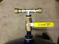
In other news...I added a pilot lamp to the mag starter to provide a ready indication of automatic operation. (Alan recommended a great lamp...but I actually had some 220V LED's at work and grabbed one for this). I also cleaned and installed two (2) brass quick connects to the output configuration until I build my "Camby Cooler"
Lastly...I have a design in mind for a sheave/pulley cover and will photodocument that process once I get the necessary materials...so stay tuned for the custome build of the cover!!!
. The pump runs awesome and pumps up even better (faster) than the specifications listed by Curtis for a 5HP motor driving an E50 pump on a 80-gallon horizontal tank.
I have been hearing a "tinging" sound; analogous to a fork lightly tapping on the side of an empty tin coffee can. What first came to mind is "Great...a rod bearing cap must have loosened up"
. I took the belts off, grabbed the flywheel and rocked it back and forth and in and out and eveything seemed tight given the simple nature of the inspection. I put the belts back on and disconnected the copper tube that goes from the output of the HP cylinder to the tank and started the compressor. Ran beautifully...no noises whatsoever.
I reconnected the copper tube and ran it again...this time with my automotive stethoscope in hand. I found the source of the noise...it was the tank check valve. I let out a sigh of relief because it eliminated the pump as the source of the noise. I again removed the copper tube and pulled the check valve. This is a rather simple device as I discovered when I disassembled the valve. I didn't see any issues per-sa and simply cleaned it, reassembled and reinstalled the check valve.
Are these check valves noisy during normal operation? It may very well be a noise that IS normal while the system is running and I just have heightened sensitivity? That was the original check valve and replacements are fairly inexpensive http://www.amazon.com/New-tank-Check-valve-compressor/dp/B00276IWWI/ref=?ie=UTF8&m=A17VS4Z36UDX1I so I have been thinking about replacing it...
In other news...I added a pilot lamp to the mag starter to provide a ready indication of automatic operation. (Alan recommended a great lamp...but I actually had some 220V LED's at work and grabbed one for this). I also cleaned and installed two (2) brass quick connects to the output configuration until I build my "Camby Cooler"
Lastly...I have a design in mind for a sheave/pulley cover and will photodocument that process once I get the necessary materials...so stay tuned for the custome build of the cover
!!!Attachments

alan camby
Well-known member
I guess your LED looks ok
brianpgriset
Well-known member
When I installed my after cooler the check valve pinging was almost completely damped by the large volume of air between the pump discharge and check (I have a knock out pot on mine). Basically was a large pulsation damper.
I wouldn't sweat it and wait till you get your after cooler done and it should all but disappear.
I wouldn't sweat it and wait till you get your after cooler done and it should all but disappear.
alan camby
Well-known member
I think your check valve noise will change or go away with the cooler install. With such a short discharge tube that you currently have, the check valve is probably reacting to each pressure pulse of the HP piston.
With the cooler, all the extra piping and cooler volume might act as a accumulator smoothing the pulse of the HP.
Just a guess, but might wait before buying a check valve.
Edit: just saw that Brian almost said the same thing.
With the cooler, all the extra piping and cooler volume might act as a accumulator smoothing the pulse of the HP.
Just a guess, but might wait before buying a check valve.
Edit: just saw that Brian almost said the same thing.
Last edited: