To avoid these ads, REGISTER NOW!

Control Wiring Discrepancy W1 W2

600SL

Well-known member
Joined
Apr 26, 2012
Messages
1,801
Location
Connecticut
I have a question about the wiring diagrams that came with my system. There appears to be inconsistency between the three pieces involved mainly on the W2 vs W1 terminal.

System Goodman 3.5 Ton 16 SEER R410A Complete Split System Heat Pump
Condensing unit GSZ160421
Air Handler ASPT47D14
Thermostat Pro 1 T721

Air handler shows to use W1. Condenser and T stat say use W2. The system is supposedly a matched system.

Also for the yellow and orange wires in the condenser diagram the yellow and orange wires are not shown going to the air handler at all. That's fine if the terminals inside the air handler are just connection points. Air handler has yellow connected to Y2 and nothing on Y1

Can anyone tell me whats up with this.

Wiring diagrams are attached.
 

Attachments

  • Condenser and Airhandler.pdf
    120.5 KB · Views: 31
  • Thermostat.pdf
    98 KB · Views: 19
To avoid these ads, REGISTER NOW!

Stuff

Well-known member
Joined
Aug 31, 2013
Messages
572
Welcome to the world of HVAC where every installation is unique and the names and colors do not always make sense. “Matched system” just means that the manufacturer has certified that the pieces work together, not that they were designed to be exclusive to one another. One piece could be manufactured 10 years earlier than the other and still be considered matched. Some call them matched systems with different manufacturer’s components if the size is compatible (e.g. 2 ton indoor coil with 2 ton outdoor compressor). Also being “matched” and registered with the AHRI shows the efficiency values needed for government tax credits.

Air handlers are designed with the intent to support electric heat using coils but are shipped without them. The installer picks what coils to use for each customer and is responsible for adding it. The wire activating the heat coil gets labeled W1. To allow two stages/levels of heat there is a second wire labeled W2. On some of Goodman’s documentation they don’t even bother to label these, only going by the colors white and brown.

For heat pump applications the air handler’s electric coils are normally used as auxiliary heat so the thermostat will only use them when it thinks that the heat pump won’t provide enough. In that case the standard is to call them W2 or AUX. In other installs the coils are used as emergency heat so only get turned on by a switch or special circumstance. This would be labeled E at the thermostat.

And yes, the Y connections at most air handlers are just tie points to make it easier to wire.
 
OP
6

600SL

Well-known member
Joined
Apr 26, 2012
Messages
1,801
Location
Connecticut
Welcome to the world of HVAC where every installation is unique and the names and colors do not always make sense. “Matched system” just means that the manufacturer has certified that the pieces work together, not that they were designed to be exclusive to one another. One piece could be manufactured 10 years earlier than the other and still be considered matched. Some call them matched systems with different manufacturer’s components if the size is compatible (e.g. 2 ton indoor coil with 2 ton outdoor compressor). Also being “matched” and registered with the AHRI shows the efficiency values needed for government tax credits.

Air handlers are designed with the intent to support electric heat using coils but are shipped without them. The installer picks what coils to use for each customer and is responsible for adding it. The wire activating the heat coil gets labeled W1. To allow two stages/levels of heat there is a second wire labeled W2. On some of Goodman’s documentation they don’t even bother to label these, only going by the colors white and brown.

For heat pump applications the air handler’s electric coils are normally used as auxiliary heat so the thermostat will only use them when it thinks that the heat pump won’t provide enough. In that case the standard is to call them W2 or AUX. In other installs the coils are used as emergency heat so only get turned on by a switch or special circumstance. This would be labeled E at the thermostat.

And yes, the Y connections at most air handlers are just tie points to make it easier to wire.

Thanks. I did get a chance to look in the air handler today and found that both W1 and W2 goes to the harness for the heating elements. However for my 10KW aux heater there is nothing connected to the W2 output of the harness on the heating element side. I assume the W2 would be connected if I had a 15KW aux heater.

Thank you
 

Ohmthis

Well-known member
Joined
Jan 20, 2013
Messages
3,026
Location
Outside of Louisville KY
I haven't ever really had much issues with wiring goodman systems. Since this is not staged heating or cooling here's the deal. I'm at work and can't draw you anything so I'm going to explain everything as best as I can.
I would jumper the Y1 and Y2 since there is no staging.
R-24v connect a red wire from the tstat r terminal to the AH r terminal. Also connect a red wire from the HP r terminal to the AH r terminal. This gives 24v to the tstat and HP.
C- 24v common connect a blue wire from the tstat c terminal to the AH c terminal. Also connect a blue wire from the HP c terminal to the AH c terminal. This gives a 24v common to the tstat and HP.
G-fan control connect a green wire from the tstat g terminal to the AH g terminal. This gives the tstat control of the blower fan.
y-compressor control connect a yellow wire from the tstat y terminal to the AH y1 terminal. Connect a yellow from the HP y terminal and the AH y1 terminal. This tells the outside unit (both in heat and AC) to come on.
O-reversing valve control. Connect an orange wire to the tstat o terminal and the AH o terminal. Connect an orange wire to the HP o terminal and the AH o terminal. This lets the tstat tell reversing valve which mode (heat or AC) its in. (Note all of the heat pumps I have worked with energize the RV in cool mode except Rheem/Ruud.)
W2-heat mode or aux heat. Connect a white wire from tstat W2 terminal to AH W1 terminal. Connect a white wire to HP w terminal to AH W1 terminal. This does a couple of things. You can put the tstat into aux heat (run the strip heat and HP). It also tells the strip heat to come on (from the HP) when the HP is in defrost mode. This keeps from blowing cold air out of the vents during defrost.
E-emergency heat. Connect a brown wire to tstat e terminal to W2 terminal. This lets you turn on the second set of strip heat if the HP and first set of strip heat can't keep up.
Ok, that was long winded and may be even a little dumbed down. Hopefully this answers your questions.
 
Last edited:
OP
6

600SL

Well-known member
Joined
Apr 26, 2012
Messages
1,801
Location
Connecticut
I haven't ever really had much issues with wiring goodman systems. Since this is not staged heating or cooling here's the deal. I'm at work and can't draw you anything so I'm going to explain everything as best as I can.
I would jumper the Y1 and Y2 since there is no staging.
R-24v connect a red wire from the tstat r terminal to the AH r terminal. Also connect a red wire from the HP r terminal to the AH r terminal. This gives 24v to the tstat and HP.
C- 24v common connect a blue wire from the tstat c terminal to the AH c terminal. Also connect a blue wire from the HP c terminal to the AH c terminal. This gives a 24v common to the tstat and HP.
G-fan control connect a green wire from the tstat g terminal to the AH g terminal. This gives the tstat control of the blower fan.
y-compressor control connect a yellow wire from the tstat y terminal to the AH y1 terminal. Connect a yellow from the HP y terminal and the AH y1 terminal. This tells the outside unit (both in heat and AC) to come on.
O-reversing valve control. Connect an orange wire to the tstat o terminal and the AH o terminal. Connect an orange wire to the HP o terminal and the AH o terminal. This lets the tstat tell reversing valve which mode (heat or AC) its in. (Note all of the heat pumps I have worked with energize the RV in cool mode except Rheem/Ruud.)
W2-heat mode or aux heat. Connect a white wire from tstat W2 terminal to AH W1 terminal. Connect a white wire to HP w terminal to AH W1 terminal. This does a couple of things. You can put the tstat into aux heat (run the strip heat and HP). It also tells the strip heat to come on (from the HP) when the HP is in defrost mode. This keeps from blowing cold air out of the vents during defrost.
E-emergency heat. Connect a brown wire to tstat e terminal to W2 terminal. This lets you turn on the second set of strip heat if the HP and first set of strip heat can't keep up.
Ok, that was long winded and may be even a little dumbed down. Hopefully this answers your questions.

That's the way its wired now with one exception. I don't have a second stage heating strip therefore nothing is on W2 in the air handler. One thing I did find out was that the compressor shuts off if I turn on Emergency mode. That kind of *****.
 

Ohmthis

Well-known member
Joined
Jan 20, 2013
Messages
3,026
Location
Outside of Louisville KY
Shutting off the compressor during Eheat is a good thing. The HP at that point isn't doing any good, but adding to the electric bill. With certain Tstats you can set things up to automatically change over to aux or Eheat. An out door temp sensor is needed. A simple thing to do is use a temp relay outside to kill the HP compressor and sends that signal back inside to turn the Aux heat/E heat. How do you want it to work?
 
To avoid these ads, REGISTER NOW!

RustyShackleford1

New member
Joined
Jul 28, 2022
Messages
2
W2-heat mode or aux heat. Connect a white wire from tstat W2 terminal to AH W1 terminal. Connect a white wire to HP w terminal to AH W1 terminal. This does a couple of things. You can put the tstat into aux heat (run the strip heat and HP). It also tells the strip heat to come on (from the HP) when the HP is in defrost mode. This keeps from blowing cold air out of the vents during defrost.
Came across this old thread trying to figure out how to wire my system, and confused about the W wire(s).

So you're saying the tstat W2 terminal, the air-handler W1 terminal, and the heat pump W terminal should all three be connected together ?
My understanding is that the HP W terminal is an output, telling the system that the heat pump is in defrost mode. But the tstat W terminal is also an output, calling for auxiliary or emergency heat. So don't those two signals conflict with each other ?
 

RustyShackleford1

New member
Joined
Jul 28, 2022
Messages
2
I believe I mistyped some. If you need more info you can PM me or make a new post. We are all here to help out.
Thanks. I'm just wondering about tying all three 'W' terminals together: the one from the thermostat, the one to the air-handler/furnace, and the one from the compressor. Seems like the one from the compressor (that says it's defrosting) and the one from the thermostat, are BOTH "outputs" - so they're maybe trying to put out different voltages (e.g. thermostat putting out 0vac because it's not calling for backup heat, but compressor putting out 24vac because it's in defrost and IS calling for backup heat). So that's a conflict, sort of like a short-circuit.
 

Ohmthis

Well-known member
Joined
Jan 20, 2013
Messages
3,026
Location
Outside of Louisville KY
That’s exactly how it is designed. If you put the Tstat in auxiliary heat, there would be 24v put on the white wire. The terminal on the AH would receive this voltage and turn on the heat strips. If the HP goes into defrost, there would be 24v put on the white wire again and the AH would again turn on the heat strips. There is no difference in potential (24v and C are opposed in potential and there for without some resistance, like a coil, will short circuit when touched) on the white wire HP to Tstat. Think of it as two switches that control one light.
 

fitter30

Well-known member
Joined
Jun 23, 2019
Messages
3,015
Location
Peace Valley,mo
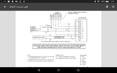
Heres your diagram. Optional outdoor stat is for bring on strip heat if hp can't keep up. But W2 if your stat is two stage will do the same.Screenshot_2022-08-09-15-29-59.png
 
To avoid these ads, REGISTER NOW!
Top Bottom