To avoid these ads, REGISTER NOW!

Copper pipe air compressor intercooler?????

hondakilla98

Well-known member
Joined
May 18, 2012
Messages
176
Location
Oregon
Copper pipe air compressor aftercooler?????

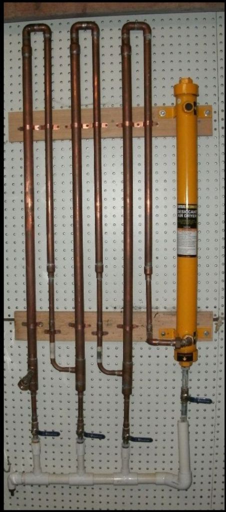
I am making some progress in my garage and I have framed a small room for my 60 gallon stand up 220V air compressor. It is 27"x40"x8'6" inside. I plan to build an intercooler out of copper pipe to go between the pump and tank that will mount on the 27"x8'6" wall. I'd like to spend about $75 total on this. I'll be making this in a "W" shape with the inlet and outlet on the top outside corners. And 2 drains, one in each low point. I'll be using 5' pieces for the legs. So I can add a leg to the "W" and have 32' of 1/2" with 3 drains. Or 21' of 3/4" with 2 drains. Here are some illustrations.

32ofcopper.png


21ofcopper.png


Also is there any advantage to making it taller with the same amount of tubing?
 
Last edited:
To avoid these ads, REGISTER NOW!

rlitman

Well-known member
Joined
Oct 18, 2010
Messages
24,591
Location
Long Island
Why don't you run it with the pipes mostly horizontal? That way you just put a filter with a drain at the end, and there are no low spots for water to collect.
 

Spudland_Dave

Well-known member
Joined
Mar 12, 2010
Messages
3,025
Location
Maine
I'm no pneumatic engineer, but I think with verticals, you'd end up alot of water in the first one, less in the 2nd, hopefully none in the 3rd...which is good..I think of it as 3 pass filtration/cooling. IF you forgot to drain a vertical one, the water would hopefully get picked up in the next section...with a horizontal, you're always passing air over/thru the water which has been collected.
 
OP
H

hondakilla98

Well-known member
Joined
May 18, 2012
Messages
176
Location
Oregon
I was thinking that I would run 5' verticals with a copper "T" in the bottom horizontal sections. Then a section of pipe about 6-12" long with a drain on the end. That way if I forget to drain it, or I'm getting a lot more water than usual it's not pushing it through to the next section. If i do that, could I just get a copper ball valve and solder it on the end of each drain pipe? I priced out the 32' copper setup with pipe, ball valves and all fittings to $70. Plus another $20 for 10' of 3/8" soft copper to connect this to my compressor. This is starting to sound expensive. Total budget is looking closer to $100 once I include hanging it and a pvc drain trough. Is this an cost effective solution or should I look at an alternative?
 
Last edited:

alan camby

Well-known member
Joined
Dec 3, 2011
Messages
1,566
Location
South of Indianapolis, Indiana
I think steel pipe will pull the heat out better.
The proper term for your cooler is a after cooler. Inter coolers are mounted between stages on a 2 stage (or more) compressor.

Several threads on after coolers if you do a search. If you spend enough time searching aftercooler you will run across a term called frazinator, or something like that.

I think you have a good plan though.
 

KinzeMech

Well-known member
Joined
Jul 15, 2012
Messages
1,164
Due to heavier mass, steel pipe will take longer to get heat soaked, but due to superior conductivity, copper will shed heat faster.
 
OP
H

hondakilla98

Well-known member
Joined
May 18, 2012
Messages
176
Location
Oregon
Here's a fitting list I made, minus the flux, solder, soft copper and ends for the soft copper. Let me know if I'm missing anything except pipe. The 90 degree street fittings will go directly into the T's on the bottom sections, Which should reduce seams and width. Since I only have 27" to work with.

fittinglist.png
 

alan camby

Well-known member
Joined
Dec 3, 2011
Messages
1,566
Location
South of Indianapolis, Indiana
Here's a fitting list I made, minus the flux, solder, soft copper and ends for the soft copper. Let me know if I'm missing anything except pipe. The 90 degree street fittings will go directly into the T's on the bottom sections, Which should reduce seams and width. Since I only have 27" to work with.

Need some kind of pipe supports.

How are you going to connect the outlet of the comp to the cooler. Need some kind of flex pipe that can handle heat.
 
OP
H

hondakilla98

Well-known member
Joined
May 18, 2012
Messages
176
Location
Oregon
I thought about using a franzinator, but this seems easier to build and probably more effective. It's definitely got more surface area and should take longer for the air to travel through.

Why I'm using copper over black pipe. Copper is slightly cheaper. I don't usually run my compressor constantly, so heat soak isn't a big deal. And copper gives me a reason to use my torch and practice soldering.
 
OP
H

hondakilla98

Well-known member
Joined
May 18, 2012
Messages
176
Location
Oregon
Need some kind of pipe supports.

I was just going to use plumbers tape to attach it to a piece of OSB with 2x2 wood stand offs to give it air space on all sides. I already have the osb, 2x2's and plumbers tape.

How are you going to connect the outlet of the comp to the cooler. Need some kind of flex pipe that can handle heat.


I was going to use 3/8" soft copper tubing with a loop in it for the inlet and outlet. That's what is running from the pump to the tank on my compressor now.
 
Last edited:

Bib Overalls

Well-known member
Joined
Dec 4, 2006
Messages
3,318
Location
Jonesboro, Arkansas
The "flow down" tubes in your drawings should extend down below the short horizontal tubes. Use a "T" fitting and not an elbow. The extended length creates a "drip leg" where water can collect. The drain valve goes at the bottom of the drip leg.

The bigger the tube the slower the air moves and that creates more opportunity for the air to cool and shed water.

You need a drip leg and drain valve at every low spot in your air lines. Air flows by pressure. Water flows by gravity. If water collects in low spots and it has no place to go it will eventually be forced down the line.

When air is compressed it gets hot and hot air holds more water than cold. When air is forced through a nozzle it gets cold (that is how refrigeration systems work). If your air tools (die grinders, angle sanders, etc.) get really cold in use and spit water your system is telling you to add more passive cooling (bigger and/or more conductive supply lines), a dryer (desiccant or refrigerated), a water separator or some combination.
 
OP
H

hondakilla98

Well-known member
Joined
May 18, 2012
Messages
176
Location
Oregon
The "flow down" tubes in your drawings should extend down below the short horizontal tubes. Use a "T" fitting and not an elbow. The extended length creates a "drip leg" where water can collect. The drain valve goes at the bottom of the drip leg.

The bigger the tube the slower the air moves and that creates more opportunity for the air to cool and shed water.

You need a drip leg and drain valve at every low spot in your air lines. Air flows by pressure. Water flows by gravity. If water collects in low spots and it has no place to go it will eventually be forced down the line.

When air is compressed it gets hot and hot air holds more water than cold. When air is forced through a nozzle it gets cold (that is how refrigeration systems work). If your air tools (die grinders, angle sanders, etc.) get really cold in use and spit water your system is telling you to add more passive cooling (bigger and/or more conductive supply lines), a dryer (desiccant or refrigerated), a water separator or some combination.

So I should put the "T" fittings in the bottom right corners and maybe tilt the whole setup 5 or 10 degrees to the right? That way my drip legs will be the low spots in each bottom section?

Are you saying I should use bigger pipe?

Would making a nozzle in each downleg help? Or would it be too small and make the pump work harder, creating more heat? Maybe putting a 1/2"-1/4" reducer after the top elbow on the down leg, an inch or two of 1/4" pipe, then another 1/4"-1/2" reducer to make a nozzle in the pipe? Like a mini franzinator in each of the three downlegs? Or maybe solder a pipe barb with a 1/4" hole in it inside the pipe in each downleg?
 

Tim The Tool Man

Well-known member
Joined
Mar 1, 2012
Messages
1,520
Location
Lehigh Valley, PA
This is a re-post from a recent thread:

Over the years I have designed some fairly elaborate custom filtration systems for the koi ponds I've installed for clients. Among the designs I have developed some pretty cool bubblers. I also dabble in HVAC on weekends with a friend, who is a pro.

Anyhow the reason I explained this is because I like to know how things work and therefore I have become knowledgeable about the venturi principle and how it can cool gasses (http://en.wikipedia.org/wiki/Venturi_effect). Take a compressed air blower nozzle and clean the dust off your saw, when you are done feel the tip, it will be cold and moist.

Because I had some spare time, copper pipe, and the wall space I can up with this gizmo:
venturi_zps5fe3e9fb.jpg


Basically, as some others have stated, it is designed to take the compressed air from a small diameter pipe and instantly move it through to a larger diameter pipe which will cool the air and allow the water to drop out of suspension. My system basically moves the air from a 3/8 nozzle into a 1" dia. pipe several times over. Here is a diagram of one of these nozzles which I brazed within the pipes:
CompVenturi_zpsfba210c3.jpg


I sold the compressor that the system was attached to and am rebuilding an old American Kellogg so there is nothing attached to it now but once everything is back together there will be, from the compressor, a 3/4" flexible hydraulic hose, a filter, then my venturi dryer gizmo, (frazinator or after cooler) then a horrible freight desiccant dryer (now discontinued), then onto my shop piping...

I might add a suggestion here since you say you are only going to use your air system intermittently. I have an idea that I will build the next time I paint a vehicle. Basically I am going to take a 25' to 50' coil of heavy gauge 5/8 copper tubing and arrange it like you might see in a still, place a tee at the end with one leg, a valve, facing downward that I can crack open and the other would go on to my paint gun. Then I'll immerse the whole contraption in a large tub filled with ice and water. I believe this would be called an ice bath but I am having no luck finding a pic on Google so I'll draw one up.. Anyhow I think this type of cooler would work??? :dunno:
icebath.jpg
 
Last edited:

cglasgow

Well-known member
Joined
Jun 12, 2010
Messages
1,139
I have an idea that I will build the next time I paint a vehicle. Basically I am going to take a 25' to 50' coil of heavy gauge 5/8 copper tubing and arrange it like you might see in a still, place a tee at the end with one leg, a valve, facing downward that I can crack open and the other would go on to my paint gun. Then I'll immerse the whole contraption in a large tub filled with ice and water. I believe this would be called an ice bath but I am having no luck finding a pic on Google so I'll draw one up.. Anyhow I think this type of cooler would work??? :dunno:
icebath.jpg


Been there, done that. It works. I submerged a water trap in mine and it would fill nearly instantly. Got to be a bit annoying emptying it but beat having water in the line.
 

djjsr

Well-known member
Joined
Sep 4, 2006
Messages
4,796
Location
In the cornfields
Here's an idea for those that have a beer refrigerator in the garage ......

Put a copper coil in that space where the bottom shelf was. You don't use that shelf anyway because your back hurts when you bend over that far right?

Drill a hole in the side for the air inlet and another hole for the outlet. A third hole and a valve for a drain from a T at the lowest point of the coil.

Maybe a couple of quick disconnects and hose whips so you can unplug it to move the refrigerator to get the stuff that you drop on the floor (most of the time it will roll under the frig). :lol:

It should work ............ shouldn't it?
 

KinzeMech

Well-known member
Joined
Jul 15, 2012
Messages
1,164
Yes, it would work, for short bursts.

The heat carrying capacity of a common refrigerator is actually quite low. It would not take much continuous running to overwhelm the fridge, although the more beer you have in the fridge, the longer it would take it to warm up.

Instead of taking a break from the air tool to allow the compressor to catch up, you'd end up waiting for your aftercooler to catch up.
 
To avoid these ads, REGISTER NOW!
OP
H

hondakilla98

Well-known member
Joined
May 18, 2012
Messages
176
Location
Oregon
This is a re-post from a recent thread:

Over the years I have designed some fairly elaborate custom filtration systems for the koi ponds I've installed for clients. Among the designs I have developed some pretty cool bubblers. I also dabble in HVAC on weekends with a friend, who is a pro.

Anyhow the reason I explained this is because I like to know how things work and therefore I have become knowledgeable about the venturi principle and how it can cool gasses (http://en.wikipedia.org/wiki/Venturi_effect). Take a compressed air blower nozzle and clean the dust off your saw, when you are done feel the tip, it will be cold and moist.

Because I had some spare time, copper pipe, and the wall space I can up with this gizmo:
venturi_zps5fe3e9fb.jpg


Basically, as some others have stated, it is designed to take the compressed air from a small diameter pipe and instantly move it through to a larger diameter pipe which will cool the air and allow the water to drop out of suspension. My system basically moves the air from a 3/8 nozzle into a 1" dia. pipe several times over. Here is a diagram of one of these nozzles which I brazed within the pipes:
CompVenturi_zpsfba210c3.jpg


I sold the compressor that the system was attached to and am rebuilding an old American Kellogg so there is nothing attached to it now but once everything is back together there will be, from the compressor, a 3/4" flexible hydraulic hose, a filter, then my venturi dryer gizmo, (frazinator or after cooler) then a horrible freight desiccant dryer (now discontinued), then onto my shop piping...

Your "gizmo" looks very interesting, and expensive. How much did that cost too build? I think I could build that for about $160 without the harbor freight drier.
 
Last edited:

Tim The Tool Man

Well-known member
Joined
Mar 1, 2012
Messages
1,520
Location
Lehigh Valley, PA
Your "gizmo" looks very interesting, and expensive. How much did that cost too build? I think I could build that for about $160 without the harbor freight drier.

I couldn't tell you how much I paid but it wasn't $160. Fortunately I am a hoarder of building materials. After I finish a job for someone I hang on to many of the extra and cut off parts. So I had most of the pipes and fittings lying around. I recall buying the valves in bulk on Amazon and the dryer was around $12.00 at HF as it was disco. But yes, buying retail you are looking at around $160...
 

KinzeMech

Well-known member
Joined
Jul 15, 2012
Messages
1,164
The best way to hook up an intercooler like that would be between the pump and the tank. It would condense out moisture before it even reaches the tank.
 

KinzeMech

Well-known member
Joined
Jul 15, 2012
Messages
1,164
Sorry, I got carried away by tim's picture. His cooler looked like it would be plugged in downstream of the tank.
 

pipsters

Well-known member
Joined
Sep 1, 2010
Messages
4,899
Location
USA
OP search for the term "aftercooler" or "after cooler" on here. There have been a couple of really long threads on the subject. The guy above though uses physics to solve the problem, which is interesting, although IMO I think it isn't working on the principle he thinks it is.

In turbine aircraft we take air compressed to very high pressure and temperature, run it through several heat exchangers cooling only with outside ambient air (could be 100*F in the summer) and using the properties of expansion deliver below freezing air. Pretty impressive.

Basic idea would be to expand the air dropping its' pressure, cool it thru a heat exchanger, then compress it again. Repeat a few times and presto you're there. Then filter out the water. Basically if you have an idea about how air conditioning HVAC works, it's the same principle. Think condenser and evaporator.

However, here's the thing - the air coming out of your compressor isn't actually compressed much to my knowledge. It only gets compressed when it's forced into a container of some sort - a compressor pump is really just a high powered air pump of sorts. So the above principle won't actually work in an after cooler situation - unless you are doing it coming off your tank after already being compressed - but your tank pressure would have to stay higher than your pressure coming out the nozzle of the tool you're using, which would be tough in a home use compressor.
 

akdiesel

Well-known member
Joined
Aug 8, 2008
Messages
2,617
Location
Wasilla, AK
OP search for the term "aftercooler" or "after cooler" on here. There have been a couple of really long threads on the subject. The guy above though uses physics to solve the problem, which is interesting, although IMO I think it isn't working on the principle he thinks it is.

In turbine aircraft we take air compressed to very high pressure and temperature, run it through several heat exchangers cooling only with outside ambient air (could be 100*F in the summer) and using the properties of expansion deliver below freezing air. Pretty impressive.

Basic idea would be to expand the air dropping its' pressure, cool it thru a heat exchanger, then compress it again. Repeat a few times and presto you're there. Then filter out the water. Basically if you have an idea about how air conditioning HVAC works, it's the same principle. Think condenser and evaporator.

However, here's the thing - the air coming out of your compressor isn't actually compressed much to my knowledge. It only gets compressed when it's forced into a container of some sort - a compressor pump is really just a high powered air pump of sorts. So the above principle won't actually work in an after cooler situation - unless you are doing it coming off your tank after already being compressed - but your tank pressure would have to stay higher than your pressure coming out the nozzle of the tool you're using, which would be tough in a home use compressor.

No and Yes. No, in regards to the air is compressed via the pump and travels down a (usally) copper pipe to the tank. This is why the copper pipe is hot due the compressed air and the piping being the same size as the discharge of the pump. No JT effect yet. When it enters the tank at a large DP the air cools fast creating a JT effect and dropping out moisture, but (here is the YES in your comment) if the DP is small the air can not be cooled correctly and the air starts to warm up in the tank. At times when we use our air it is in small amounts that the DP will not be high enough to create a JT and it will travel down the air lines to the users and as someone mentioned in here or another thread the tool will vent the air when being used creating it's own JT and the tool will cool quickly and may drop moisture out it's vent since the earths air pressure at sea level is approx 14 psi and the air in the lines should be above 90 psig.
 

pipsters

Well-known member
Joined
Sep 1, 2010
Messages
4,899
Location
USA
No and Yes. No, in regards to the air is compressed via the pump and travels down a (usally) copper pipe to the tank. This is why the copper pipe is hot due the compressed air and the piping being the same size as the discharge of the pump. No JT effect yet. When it enters the tank at a large DP the air cools fast creating a JT effect and dropping out moisture, but (here is the YES in your comment) if the DP is small the air can not be cooled correctly and the air starts to warm up in the tank. At times when we use our air it is in small amounts that the DP will not be high enough to create a JT and it will travel down the air lines to the users and as someone mentioned in here or another thread the tool will vent the air when being used creating it's own JT and the tool will cool quickly and may drop moisture out it's vent since the earths air pressure at sea level is approx 14 psi and the air in the lines should be above 90 psig.

The reason moisture comes out the tool is because the air is cooled below the dew point - has nothing to do with the PSI differential in the out coming air vs. ambient pressure.

Hence why you want to cool the air, take the moisture out, then put it in the system.

OP you might find this an interesting read as well

Building an El-Cheapo Compressed Air Dryer PDF
 

alpinewhite

Well-known member
Joined
Aug 4, 2012
Messages
1,315
Location
Orange County, California, USA
hondakilla98,

On the way to the Venturi2, the air is compressed again, thus, turning the liquid water into vapor again. The output of Venturi2's isn't gonna be any cooler than the output of Venturi1 less the normal heat loss from the pipe between V1 and V2 so I don't expect Drain2 to collect any liquid. The same situation applies on the way to V3.

A good experiment is to see if there is actually any water collected in Drain2 and Drain3.

Just my 2 cents.
 
Last edited:
OP
H

hondakilla98

Well-known member
Joined
May 18, 2012
Messages
176
Location
Oregon
I'm thinking to save cost I might do the first leg as tttm has in his picture, then just do 1/2" copper for the second 2. With 5' of 3/8" soft copper for the inlet and outlet, I'll have a little over 40 ft of pipe between my pump and tank. Should I have a filter between the aftercooler and tank? After the tank? Or both? I'll be running a basic 1/2" maxline kit to distribute air around my 2 car garage.
 

akdiesel

Well-known member
Joined
Aug 8, 2008
Messages
2,617
Location
Wasilla, AK
The reason moisture comes out the tool is because the air is cooled below the dew point - has nothing to do with the PSI differential in the out coming air vs. ambient pressure.

Hence why you want to cool the air, take the moisture out, then put it in the system.

OP you might find this an interesting read as well

Building an El-Cheapo Compressed Air Dryer PDF

I understand due point rules. Simply stating when using air tools the restriction is at the tool and not the tank so the tank air will be warm and travel down the air line to the tools, so when it powers the tool it does JT. A standard air compressor system does not have the means of removing liquid when working under load, thus the reason for a good desiccant system or cooler and liquid trap system.
 
OP
H

hondakilla98

Well-known member
Joined
May 18, 2012
Messages
176
Location
Oregon
I found a B&M Super Cooler 11"x11" on CL for $50. Now that I'm seeing how effective something like that can be with a fan. Where should I look for a reasonably priced 230v fan?
 

brianpgriset

Well-known member
Joined
Sep 29, 2006
Messages
1,042
Location
Beaumont, TX
I found a B&M Super Cooler 11"x11" on CL for $50. Now that I'm seeing how effective something like that can be with a fan. Where should I look for a reasonably priced 230v fan?

Search "ebm papst" on eBay. Many size and voltage options. I got mine for $40 shipped.
 
Last edited:
OP
H

hondakilla98

Well-known member
Joined
May 18, 2012
Messages
176
Location
Oregon
I've found some 230v axial fans that should work, but I'm not sure how many cfm I should be looking for. Most of the ones under $50 are 6-8" fans in the 200cfm range. I did find a pair of 5" fans for $50 shipped that are each 190 cfm. This will be going on an 11" square cooler. I wont be making a shroud for this, they will just be mounted to the cooler and blow through. What about a 10" electric radiator fan for a car? Maybe run an inverter to get 12v dc? I've seen some of them that are rated close to 1000 cfm for around $50.
 

alan camby

Well-known member
Joined
Dec 3, 2011
Messages
1,566
Location
South of Indianapolis, Indiana
I've found some 230v axial fans that should work, but I'm not sure how many cfm I should be looking for. Most of the ones under $50 are 6-8" fans in the 200cfm range. I did find a pair of 5" fans for $50 shipped that are each 190 cfm. This will be going on an 11" square cooler. I wont be making a shroud for this, they will just be mounted to the cooler and blow through. What about a 10" electric radiator fan for a car? Maybe run an inverter to get 12v dc? I've seen some of them that are rated close to 1000 cfm for around $50.

I used a fan from Mcmaster-carr.
part#1976k98 It is 600cfm
http://www.mcmaster.com/#standard-equipment-cooling-fans/=jjsy50
 

brianpgriset

Well-known member
Joined
Sep 29, 2006
Messages
1,042
Location
Beaumont, TX
I've found some 230v axial fans that should work, but I'm not sure how many cfm I should be looking for. Most of the ones under $50 are 6-8" fans in the 200cfm range. I did find a pair of 5" fans for $50 shipped that are each 190 cfm. This will be going on an 11" square cooler. I wont be making a shroud for this, they will just be mounted to the cooler and blow through. What about a 10" electric radiator fan for a car? Maybe run an inverter to get 12v dc? I've seen some of them that are rated close to 1000 cfm for around $50.

The ebm one I got off eBay was rated at 600cfm. 200 isn't enough. The more the better. I would not get less than 500cfm.
 
To avoid these ads, REGISTER NOW!
Top Bottom