To avoid these ads, REGISTER NOW!

Correct wire size for Quincy install

Tarnished

Well-known member
Joined
Feb 8, 2012
Messages
721
Location
SW Ohio
Need to pull new wire for Quincy 325. Motor is 5hp, 3ph drawing 15.2a, and is approx 60 feet from source. Will #10 stranded copper work, or should I go to #8 for a compressor at this distance? Need to purchase wire.
Thanks.
 
To avoid these ads, REGISTER NOW!

superdel

Active member
Joined
May 3, 2012
Messages
38
#10 will do just fine. At 15 amps, you can even use #12. Just make sure the wire size matches the breaker. If you are using a 20 amps breaker, #12 is OK. If you are using a 30 amp breaker, which I would suspect that you are, go with #10. 8 is overkill and more expensive.
 
OP
T

Tarnished

Well-known member
Joined
Feb 8, 2012
Messages
721
Location
SW Ohio
Thanks super,
Glad for confirmation. Perhaps you can keep me on track with wiring starter.
Let me see if I have this correct:
220V 3ph coming directly from RPC would land on terminals L1, L2, L3.
This in turn would be fed thru Mag Starter when energized to T1, T2, T3 directly to motor. Motor rotation could be reversed by changing L1 & L2 if needed.
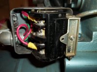
Now the tricky part: To wire in the compressor pressure switch, I would need to install jumper between post 3, and aux interlock terminal on starter. Then run a lead from term 3, to the pressure sw, and return from pressure sw. to term 1. This would allow n.o. contact on pressure sw to close mag starter as needed.
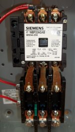
Pics should help.
Have I got this correct, or have I lost track somewhere?
Thanks for your help.
 

Attachments

  • mag starter.JPG
    mag starter.JPG
    95.9 KB · Views: 27
  • Starter diag.JPG
    Starter diag.JPG
    133.5 KB · Views: 23
  • Pressure sw.JPG
    Pressure sw.JPG
    105.4 KB · Views: 20
  • pressure sw wire.JPG
    pressure sw wire.JPG
    114.7 KB · Views: 20

Norcal

Well-known member
Joined
Mar 16, 2008
Messages
13,792
Just a note: the manufactured leg off the RPC should not be used for the control circuitry, & needs to be identified. & yes, your leads from the pressure switch go to terminals 1 & 3 on the mag starter.
 

superdel

Active member
Joined
May 3, 2012
Messages
38
The power coming in goes to L1,L2,L3. This is called Line. The T leads go to the motor. If the rotation is wrong, you can change it by swapping any 2 leads, either L or T. Generally speaking, you swap any 2 T leads. It is usually easier to get at and can be done at either the starter, or motor.
I was thinking you were using 480 3 phase. But at 220, a 5 hp motor will draw about 13 amps. So, you can easily use 12 gauge wire. Again, depending on your breaker. If there is a 20 amp breaker in the panel, then 12 is sufficient. If there is a 30, then use 10.
Let me get back to you on the wiring questions when I get a chance to look at the pictures.
 
To avoid these ads, REGISTER NOW!

superdel

Active member
Joined
May 3, 2012
Messages
38
I need to know a few things. What is the coil voltage? Are you going to run this with an off/on switch, or are you going to use the disconnect to shut it on or off? This info will determine how to wire the starter.
 
OP
T

Tarnished

Well-known member
Joined
Feb 8, 2012
Messages
721
Location
SW Ohio
Super,
3ph power will come from a 7.5hp Phasemaster RPC Mounted in top of barn, fed approx 60 feet with #10 copper in conduit, to a new 3ph non fused disconnect (sorry no pic, but M/N is Siemens HNF361) mounted above new compressor location. Will go from this disconnect to the Siemens Mag Starter (M/N 16BF32AGAB with heater E60 (not install in pic), and 240V Coil) Land on L1, L2, L3. T1, T2, T3 will then go to the motor. I plan on having the compressor turn on automatically with the pressure switch. To do this I need to tie the leads (2) from the pressure switch down to terminals 3 and 1 on starter. I will also have to add a jumper from terminal 3, and the aux interlock on the starter, IF I am reading the diagram correctly. How am I doing so far?? If I need to stop the compressor, I can use the disconnect to shut it down for maint etc. Although this doesn't give me a start button, I not sure I need one to turn it on manually. Pressure switch should take care of this automatically, and if I HAD to, I could bleed it down to kick in the low pressure. At least this is my thoughts. Please tell me if I am in left field. Nothing has been started, so can change anything on paper easy!
Sure don't' want any melt downs. :scared:
You are correct it is fused at 30a. Appreciate the help, and let me know if you need any further pics.

Norcal, Not sure I understand using generated leg for control? As in not having it on L1, or L2? That way it is not used to control coil? Or ???
Trying to understand something that is not my field. Thanks guys for your help.
 

Norcal

Well-known member
Joined
Mar 16, 2008
Messages
13,792
You should have 2 legs measuring 120 volts line to ground (your single phase 240 volt input), the manufactured leg should read around 208 volts, and 240 volts line to line, I prefer to treat a RPC's output like 240 volt 3Ø and use L2 for the manufactured leg off the RPC, 240V 3Ø is required to have the high leg as the "B" phase, it is not required for a RPC, but I prefer it that way...

Maybe I should post the NEC requirements for a RPC???
 

superdel

Active member
Joined
May 3, 2012
Messages
38
240 volt coil and no start button makes life pretty simple. It also takes Norcal's question out of the equation. You also do not have to deal with the aux contact. The 3 wires from the disconnect will go to L1,L2,L3. The T leads go to the motor. Just to be consistent with the starter schematic that you have, runa wire from L2 to X2 and one from NC to #1 of the coil. Run a wire from L1 or L3 (doesn't make any difference) to one side of the pressure switch. From the other side of the pressure switch, return to #3 of the coil. Make sure the pressure switch is rates to handle 240 volts and that it is a closed contact on low pressure and opens up on high pressure. Since it is a 240 volt coil, you are using the top picture for pilto devices. Just a simple control device to cycle the compressor. Schematically it is a single line starting from L1 to the normally closed pressure switch, from the pressure switch to #3 of the coil. The other side of the coil is #1. This goes to a normally closed contact that is your overload circuit. The other side of is X2 and goes to coil # 1 giving you the 240 volts across the coil when the circuit is made. The coil isn't reference to ground so you don't have to worry about the "crazy" leg. The motor will shut off if the overloads open up, or the pressure switch opens up when the demand is met. I can draw it for you and email it to you on Monday from work if you like. Or if you have more questions and would like to email me, not a problem. PM me and I will give you the address. Hope this helps.
 
OP
T

Tarnished

Well-known member
Joined
Feb 8, 2012
Messages
721
Location
SW Ohio
Thanks Super,
Makes sense to me, now i have to go take a close look at the starter and p switch. This will determine how much I think I understand. LOL...
Will let you know how I make out.
Appreciate your help.
 
To avoid these ads, REGISTER NOW!
Top Bottom