To avoid these ads, REGISTER NOW!

Craftsman block grinder help

M. Blue 240

Well-known member
Joined
Nov 8, 2011
Messages
261
Location
Beaverton, OR
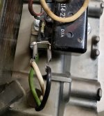
20201204_203221 by M. Blue 240, on Flickr

I picked this great grinder off CL. The seller stated I was 2nd in line, but then told me I could have it for free. The first buyer showed up and walked away from it when it threw the garage breaker when they tested it. With the promise to fix it the grinder was mine. I inspected it and found an exposed wire on the stator. When I posted here asking about repairing the stator FrankLee was nice enough to send me a known good stator to drop in. I replaced the stator and it kicked my GFI socket (my existing grinder functions fine on this socket). There isn't much in the way of wiring, so I replaced the power cord with a brand new one and it again threw the GFI.

I'm not super knowledgeable when it comes to electrical, so I'm looking for tips on where to inspect or how to test.

These are the pics I took to ensure I plugged it all back together. You can see the exposed wire from the stator.

20210122_150414 by M. Blue 240, on Flickr

20210125_114205 by M. Blue 240, on Flickr

20210125_114228 by M. Blue 240, on Flickr

20210128_115901 by M. Blue 240, on Flickr

This is my current workhorse that's waiting for the new unit to run so it can get a refresh of its own.

20210128_115919 by M. Blue 240, on Flickr
 
To avoid these ads, REGISTER NOW!

exmaxima1

Well-known member
Joined
Jun 25, 2011
Messages
6,341
Location
Midwest
GFI pops when there is an electrical path to ground, so I would suspect that a burnt winding is shorting to the stator metal assembly. A multimeter on the ohms setting should be able to verify that very easily.
 

torqueman2002

Well-known member
Joined
Jun 3, 2009
Messages
6,141
Location
SE Michigan
Here's a wiring diagram for your model Block grinder, with resistance values for the windings/stator. The leads of course need to be disconnected.

attachment.php
 

Attachments

  • P1100070 a.jpg
    P1100070 a.jpg
    81.1 KB · Views: 120
To avoid these ads, REGISTER NOW!

torqueman2002

Well-known member
Joined
Jun 3, 2009
Messages
6,141
Location
SE Michigan
I think I see the problem.

The power and neutral from the power cord are connected to the same terminal of the relay.

The black/power wire from the power cord should go to the power switch. The white/neutral wire from the coils goes to the other terminal of the power switch.

The ground (Green) wire, is bolted to the frame.

attachment.php
 

Attachments

  • Capture Relay Wiring a.JPG
    Capture Relay Wiring a.JPG
    48 KB · Views: 116
Last edited:

macgee

Well-known member
Joined
Jan 11, 2014
Messages
2,834
Location
Sepulveda Pass, CA
Good eye Torque, that would very much be considered a non-friendly breaker situation.

PS> I use that exact same Veritas note pad as well


Non-related to the tripping but I'm going to assume that red wire I see in the earlier pics has been replaced?
 
OP
M

M. Blue 240

Well-known member
Joined
Nov 8, 2011
Messages
261
Location
Beaverton, OR
I didn't even think of that when I was putting it back together, just copied the way it had been. Thanks for catching that! I'll dig in this weekend and try to spot the right connections.
 
To avoid these ads, REGISTER NOW!
Top Bottom