I recently picked up a non-working 1/2 HP Craftsman "block" grinder 397.19370 so I could get my good running 1/2 HP 397.19430 usable. Only difference I can see in them is the 19430 has a light. Anyways figured I would check the "bad" bench grinder. Plugged it in and it started right up and was even quieter than the "good" one! Thinking cool one for a buffer and one for a grinder. Then turned it on again and no dice, made noise but didn't turn. Tried spinning the wheel as fast as possible and then hitting the "on" switch but that made it stop almost immediately! So trying to figure out what's wrong. Pulled bottom cover off, no sign of any problems there. Wiring looks fine. Only thing I can figure is the starting relay is bad but I am no expert. The relay is no longer available from Sears. Anybody have any ideas?

You are using an out of date browser. It may not display this or other websites correctly.
You should upgrade or use an alternative browser.
You should upgrade or use an alternative browser.
Craftsman block grinder troubleshooting
- Thread starter bluebolt
- Start date
bgott
Well-known member
Get the specs off of the old cap and look in the Grainger catalog.
Bgott, this is the newer one without a capacitor.
So I am playing with it again today and it starts fine. Whatever problem it has it's intermittent. It is much noiser than the good one on startup but quiet when it's up to speed. I am researching a source for the relay, its marked F8A 4CR-20-728. Sears doesnt carry it anymore.
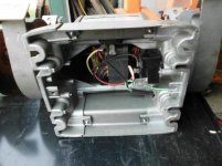
Here's a few pics of the grinders. The red label one with the lamp is the "good" one, the gold label one is the "intermittent" one.
The red label one starts up nice and is fairly quiet. It was missing the eye shields, one tool rest, one wheel cover and the left wheel guard is bent from being dropped. It did not have a water tray.
The gold label one was complete including the water tray. The left wheel guard on this one is also bend from being dropped. OK guys make sure your grinder is mounted secure!
Luckily the wheel guards (and wheel covers) fit either side. I will be able to make at lleast one good grinder and maybe use the other as a buffer without shields.
So I am playing with it again today and it starts fine. Whatever problem it has it's intermittent. It is much noiser than the good one on startup but quiet when it's up to speed. I am researching a source for the relay, its marked F8A 4CR-20-728. Sears doesnt carry it anymore.
Here's a few pics of the grinders. The red label one with the lamp is the "good" one, the gold label one is the "intermittent" one.
The red label one starts up nice and is fairly quiet. It was missing the eye shields, one tool rest, one wheel cover and the left wheel guard is bent from being dropped. It did not have a water tray.
The gold label one was complete including the water tray. The left wheel guard on this one is also bend from being dropped. OK guys make sure your grinder is mounted secure!
Luckily the wheel guards (and wheel covers) fit either side. I will be able to make at lleast one good grinder and maybe use the other as a buffer without shields.
Attachments


Last edited:
The relay contacts are most likely wore out, so sometimes they work, other times they don't.
When the grinder fails to start, do you hear/feel a click in the relay just as you power the grinder up? If so, then the relay tries to work, but doesn't due to the worn contacts.
The relay has three wires on it. 1 in, two out. Of the two out terminals, one goes to the starter winding, the other to the main winding.
You can put a volt meter on the neutral wire, and the other probe on the terminal going to the starter winding. Set meter for 200V AC (or whatever the suitable range is on your meter).
Power up the grinder. You should ideally see 120V AC reading on the meter, but might be less due to worn relay contacts. If the grinder turns and starts up, you'll see it drop to 0V within a second or two. If the grinder fails to turn, you'll probably see 0V or at least a very low voltage. This means the relay isn't passing the voltage, again due to wore out contacts.
Here's the data sheet for the relay, btw: http://www.sensata.com/download/4cr.pdf
Basically, odds are 99% it's the relay that's just wore out. A intermittent connection in the start winding is also a possibility, but highly unlikely.
You can bypass the relay temporarily to see if the grinder starts up that way. Just unhook the wire that goes to the start winding and hook it to the incoming line wire. Flip the switch, and it should start spinning. Don't leave it running like this, though, as you'll overheat the start winding.
You can hold the start winding terminal to the hot line while switching on the grinder, then once it starts spinning, remove the start winding terminal from hot. At this point it's okay to leave it running.
Don't electrocute yourself.")
When the grinder fails to start, do you hear/feel a click in the relay just as you power the grinder up? If so, then the relay tries to work, but doesn't due to the worn contacts.
The relay has three wires on it. 1 in, two out. Of the two out terminals, one goes to the starter winding, the other to the main winding.
You can put a volt meter on the neutral wire, and the other probe on the terminal going to the starter winding. Set meter for 200V AC (or whatever the suitable range is on your meter).
Power up the grinder. You should ideally see 120V AC reading on the meter, but might be less due to worn relay contacts. If the grinder turns and starts up, you'll see it drop to 0V within a second or two. If the grinder fails to turn, you'll probably see 0V or at least a very low voltage. This means the relay isn't passing the voltage, again due to wore out contacts.
Here's the data sheet for the relay, btw: http://www.sensata.com/download/4cr.pdf
Basically, odds are 99% it's the relay that's just wore out. A intermittent connection in the start winding is also a possibility, but highly unlikely.
You can bypass the relay temporarily to see if the grinder starts up that way. Just unhook the wire that goes to the start winding and hook it to the incoming line wire. Flip the switch, and it should start spinning. Don't leave it running like this, though, as you'll overheat the start winding.
You can hold the start winding terminal to the hot line while switching on the grinder, then once it starts spinning, remove the start winding terminal from hot. At this point it's okay to leave it running.
Don't electrocute yourself.
The relay contacts are most likely wore out, so sometimes they work, other times they don't.
When the grinder fails to start, do you hear/feel a click in the relay just as you power the grinder up? If so, then the relay tries to work, but doesn't due to the worn contacts.
The relay has three wires on it. 1 in, two out. Of the two out terminals, one goes to the starter winding, the other to the main winding.
You can put a volt meter on the neutral wire, and the other probe on the terminal going to the starter winding. Set meter for 200V AC (or whatever the suitable range is on your meter).
Power up the grinder. You should ideally see 120V AC reading on the meter, but might be less due to worn relay contacts. If the grinder turns and starts up, you'll see it drop to 0V within a second or two. If the grinder fails to turn, you'll probably see 0V or at least a very low voltage. This means the relay isn't passing the voltage, again due to wore out contacts.
Here's the data sheet for the relay, btw: http://www.sensata.com/download/4cr.pdf
Basically, odds are 99% it's the relay that's just wore out. A intermittent connection in the start winding is also a possibility, but highly unlikely.
You can bypass the relay temporarily to see if the grinder starts up that way. Just unhook the wire that goes to the start winding and hook it to the incoming line wire. Flip the switch, and it should start spinning. Don't leave it running like this, though, as you'll overheat the start winding.
You can hold the start winding terminal to the hot line while switching on the grinder, then once it starts spinning, remove the start winding terminal from hot. At this point it's okay to leave it running.
Don't electrocute yourself.
LOL on the electrocution,
When I put the voltmeter from the black 'in" wire on the switch to the white "in" wie on the relay I get 124 volts.
Black "in" to Black "out" on relay 0 volts
Black "in" to red "out" on relay 177 volts
White "in" to black "out" on relay 124 volts.
White "in" to red "out" on relay 117 volts
Both grinders give these readings. Must be something to do with the split phase deal.