Just wanted to post another update on my progress.
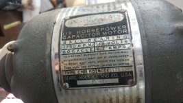
For background, I am restoring a Model 100 (P/N 103.23131). The date code from the original motor is 4/54. So I will assume this particular DP was built in 1954. I purchased this drill press from a fellow local Garage Journal member,
Smokeshow69. (Thanks again for the deal

)
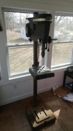
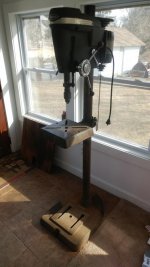
Here is what I started with:
**NOTE that the broken vari-slo was not included in the sale, so I do not have that**
I now have the DP completely disassembled (with the exception of the motor) and have started to clean it up and polish some of the part.
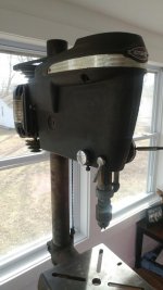
First we have the head. Overall it cleaned up pretty well. I pressure washed it inside and out, sprayed it down with degreaser & mineral spirits and scrubbed it with wire brushes and green scotch-brite pads. There is some light rust in spots and the original paint is worn through in some areas (near the top). There is also some very stubborn paint splatter on one side. The wire brushing, mineral spirits, scotch-brite scrubbing etc didn't touch that white paint splatter.
I am at a crossroads here as I am still undecided if I will repaint it or keep the patina. If I don't repaint it I really need to remove the white paint splatter but don't want to further damage the finish. Maybe I will try a fresh razor blade and attempt to scrape 'em off carefully.
The column base and tilting table also cleaned up pretty well. The biggest challenge so far was removing the taper pin from the tilt table. (see my previous post (
https://www.garagejournal.com/forum/showpost.php?p=7687770&postcount=2292). The cleaning of the machined surface of the table uncovered some "arc-of-shame" holes that were not apparent when it was covered in barn dust. Fortunately, the errant drill holes are minimal and will not impact usability at all.
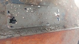
Also, despite the warnings on this forum, I "accidently" removed all the finish from the data plate on the column base. Interestingly, though, I used no harsh chemicals/solvents... nor did I use a brush. I wiped it with soapy water and a shop towel and the finish came right off.
So I am not sure there was any way for me to have cleaned that without ruining it. OH WELL!.
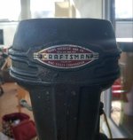
As for the head band + badge. The headband was pretty dirty and had some of the same white paint splatter on it. I wiped it with laquer thinner and it sort-of cleaned up, but not really. I then tried some cleaner wax I had, and the finish was still very dull. Finally, I tried some very light metal polish (Blue Magic) in one area and it polished the "turning" away immediately.... even using very light pressure. OOOPS!

(no pictures, sorry).
Not sure what I will do now. I don't care for the appearance of the "engine turned" vinyl wrap so I may just give the headband a brushed finished. The head badge, however is in good shape. I don't think I will do any additional cleaning or repair to it.
I also spent a little bit of time cleaning up the quill lock handle and return spring tension knob. They are pretty severely pitted and rough. I am not sure where I want to go with these. If I try to remove the "bumps" caused by the pitting with light sanding/wire wheeling, I will further damage the good chrome.
So I think my two options would be strip the original chrome off completely and hand polish them back to a mirror shine (A ton of work and it will oxidize quickly) or I call it good enough and apply a coat of wax and move on.
As for the motor, I have not touched it beyond plugging it in to see if it works... and it does. The bearings are noisy and will need to be cleaner or replaced. As I am already replacing the quill and spindle bearings, I will likely replace the motor bearings as well. I will tear the motor down and give it a good cleaning, service the wiring, replace the cord and the bearings. I may or not repaint it... that will all depend on what I do with the rest of the drill press finish.
One thing is for sure, the decorative middle band is likely beyond repair. It is rusty and heavily pitted. I doubt it will clean up well.


 No evidence of cracks on either piece.... but damn that taper pin was stuck.