Ok I've been thinking about this and I think I got the perfect solution, that is if the product works as good as I've seen it shown.
I remember a product I saw on TV like 15 years ago called Alumaloy. It's like a brazing rod of aluminum alloy and is damn near as strong as aluminum (39,000 PSI vs regular aluminum at 42,000). But the kicker is that the melting point is like 728F compared to regular aluminum at 1220 F. Another benefit is that it doesn't stick to steel (unless it's galvanized).
Ok so here is the process.
Get a steel rod to act like a plug and help mold the ends of the spline. Actually if you are going to do this process just forget the plug and alumaloy the whole interior of the pulley (making splines the whole length of the pulley shaft.)
Alumaloy the interior of the shaft.
Bore out the inner diameter (need to do it on a lathe to center it).
Then using a shaper, rotary broach, etc make the interior splines.
Done and it as good as new if not better if you do the longer splines.
Now this should also work for shafts that are worn due to inner races spinning.
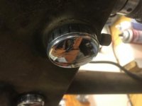
Add alumaloy around the entire area that is worn down and just chuck it up in a lathe and turn it down to the correct diameter. I mic'd 0.984" (inner diameter of bearing is 0.98425")
Product sells for $30 a lbs on amazon.
And I found the old infomercial: