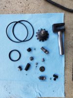
I need help putting my power unit back together. When I took it apart the oil held all the check balls in and they fell out when I tipped it over to drain the oil. I KNOW!!! My fault. Its a model 214.50145. I cant find any info on it. I have 1 PDF but the power unit parts are slightly different. I dont have some of the pointed pistons, i think mine uses 2 check balls in 1 hole?

You are using an out of date browser. It may not display this or other websites correctly.
You should upgrade or use an alternative browser.
You should upgrade or use an alternative browser.
Craftsman floor jack rebuild help
- Thread starter R1Rider
- Start date

ex-x-fire
Well-known member
https://www.garagejournal.com/forum/showthread.php?t=51105 This should help you.
https://www.garagejournal.com/forum/showthread.php?t=51105 This should help you.
ummm noooo.... that is a different power unit. There are hundreds of different power units.
paulsomlo
Well-known member
Try this link: http://i.imgur.com/wzdg53i.jpg
The working valve takes two balls, smaller one first, then the larger one. The correct size for the smaller one will drop through the upper hole, but not through the lower one.
The working valve takes two balls, smaller one first, then the larger one. The correct size for the smaller one will drop through the upper hole, but not through the lower one.
ajchien
Well-known member
I need help putting my power unit back together. When I took it apart the oil held all the check balls in and they fell out when I tipped it over to drain the oil. I KNOW!!! My fault. Its a model 214.50145. I cant find any info on it. I have 1 PDF but the power unit parts are slightly different. I dont have some of the pointed pistons, i think mine uses 2 check balls in 1 hole?
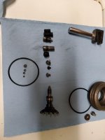
To OP - it’s hard to see ... What is the round black piece on the bottom right of the second picture beneath the short spring? Is it a needle valve (cone shaped with a stem on it, like a pine tree shape)?
Last edited:
paulsomlo
Well-known member
To OP - it’s hard to see ... What is the round black piece on the bottom right of the second picture beneath the short spring? Is it a needle valve (cone shaped with a stem on it, like a pine tree shape)?
I think that's a piece that's interposed between the spring above it and a ball. This jack is one of those "two speed" pumpers that gets you to the load quickly. The large spring is associated with the safety overload, the small one is the bypass for the speed pump function.
That jack was apparently also badged by Omega: https://www.hcrcnow.com/uploads/drawings/omega25030magicliftfloorjack3ton.pdf
ajchien
Well-known member
I think that's a piece that's interposed between the spring above it and a ball. This jack is one of those "two speed" pumpers that gets you to the load quickly. The large spring is associated with the safety overload, the small one is the bypass for the speed pump function.
That jack was apparently also badged by Omega: https://www.hcrcnow.com/uploads/drawings/omega25030magicliftfloorjack3ton.pdf
If that piece is the “adapter” between the spring and a ball valve ...
I’m looking for a combination of 5 valves (balls or needles) One for release, two for working valve, one for overload, and One for speed.
In his picture I only see 4 ball valves, no needle valves. Is he missing a piece?
paulsomlo
Well-known member
Could be - the end of the release valve doesn't appear to have a bright spot where it makes contact. Maybe the ball is still in the hydraulic block.
my power unit has 5 holes on top plus 1 screw hole. the picture you are showing has only 4 holes and 1 screw hole. the screw hole just holds a washer that stops the gear from coming out of the body. I need pictures of an identical power unit.
I'm guessing that this is similar to mine. Instead if having the pointed plunger, mine uses 2 check balls.
https://www.hcrcnow.com/uploads/drawings/sears50145floorjack3.5ton.pdf
https://www.hcrcnow.com/uploads/drawings/sears50145floorjack3.5ton.pdf
paulsomlo
Well-known member
It looks like your missing the conical piece from the overload. In your latest link, it's the lower most piece in the stack next to the plunger. It may still be inside the jack.
paulsomlo
Well-known member
The third part down from the release valve in your pic in post #1 - that fits in the end of the overload spring, presumably. I think there should be a medium size ball that goes between that part and the overload seat. I don't think that part interfaces directly with the seat - if the seat is conical, then you're missing a ball. If the seat is flat, maybe there is no ball. Do you see a mark on the bottom of that 3rd part down, where a ball may have been sitting? It looks like the smallest ball goes with the release valve, the large one and a medium one with the working valve, and I'm assuming a medium sized ball with the speed valve. Or maybe there's no ball associated with the speed valve?
Indexmill
Well-known member
Sorry OP; but if you took that all apart without taking lots of pictures or somehow keeping track of where everything goes, I am not sure that you should be rebuilding it...
Sorry OP; but if you took that all apart without taking lots of pictures or somehow keeping track of where everything goes, I am not sure that you should be rebuilding it...
lol I can rebuild just about anything. When I took this apart, I dug the parts out of he holes but was unaware there were check balls and other small parts in there. the oil was hiding them and they were stuck in the bottom and fell out when I tipped it to drain the oil. Yeah, my mistake but I was also unaware that it was going to be near impossible to find any information about repairing it online. Even Sears' literature on it is f***ing toilet paper.
The third part down from the release valve in your pic in post #1 - that fits in the end of the overload spring, presumably. I think there should be a medium size ball that goes between that part and the overload seat. I don't think that part interfaces directly with the seat - if the seat is conical, then you're missing a ball. If the seat is flat, maybe there is no ball. Do you see a mark on the bottom of that 3rd part down, where a ball may have been sitting? It looks like the smallest ball goes with the release valve, the large one and a medium one with the working valve, and I'm assuming a medium sized ball with the speed valve. Or maybe there's no ball associated with the speed valve?
I am going to lay the parts out and put numbers next to them so is easier to figure this out.
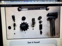
This appears to be the only possible way it can go together. The pic with the wrench in it is from Craftsman PDF manual. 1st pic shows all the parts I have lined up for refereance. 2nd pic shows what I believe to be the only possible way for it to go based on the size of the parts and size/depth of holes and passages and threads. Hole on far right is for the pumper piston, nothing goes in there. Center hole where there is the threaded hole above it is for the gear. The bottom of the pointed end of the gear has a worn dimple from a bearing. In the bottom of the hole it goes in there is also a small worn dimple on the center tube that goes up the piston. The smallest check ball is the only 1 that could have made both of those marks so I am 100% sure the smallest ball goes there. Its also too small to go in any of the other holes, it just wouldnt make sense to have a ball that small in any of them. The rest of the parts I just used process of elimination based on part size. big spring and big plunger wont go in the smaller holes so eliminated those as an option.
next question is, how do I adjust the jack?
next question is, how do I adjust the jack?
Attachments

reassembled it, filled it with oil and it doesnt work. Surprise. lol I have no pressure to the pump, I can hear air squishing around in there. I worked the piston in and out to bleed it but that did nothing. I have oil leaking past o'rings on the adjusters. You'd think it would still build some pressure. I may have screwed up on the oil filling, I didnt fill it on the bench, i filled it through the rubber plug hole after I assembled the jack.
ajchien
Well-known member
Third picture of post #19, middle column of parts ... needs 2 balls.
paulsomlo
Well-known member
There's a ball missing - I've circled where it goes in the attached pic. That's the working valve, there needs to be two balls there, upper and lower. I notice that the release valve (part with the gear) has a wear band near it's end - could you take a close up of the pointed end?
I don't know if I asked this before - did the jack work prior to disassembly?
I don't know if I asked this before - did the jack work prior to disassembly?
Attachments

paulsomlo
Well-known member
Third picture of post #19, middle column of parts ... needs 2 balls.
Wish I were stuck on the 60 today, AJ - it's 13 degrees here and snowing.
HCRCnow
Well-known member
Hello, remove the tiny ball under the release valve. The release does not use a ball. The point is the valve.
californiamilleghia
Well-known member
is there a "Master thread" to fix the pumps in old floor jacks ?
other than new ones are so cheap at HF , it seems its only a few parts to get the old ones working again.....
Or am I missing something ?
thanks
other than new ones are so cheap at HF , it seems its only a few parts to get the old ones working again.....
Or am I missing something ?
thanks
paulsomlo
Well-known member
If it's an import: https://www.garagejournal.com/forum/showthread.php?t=51105&highlight=jack, otherwise search on the brand/model of the jack, you're bound to find it here.is there a "Master thread" to fix the pumps in old floor jacks ?
other than new ones are so cheap at HF , it seems its only a few parts to get the old ones working again.....
Or am I missing something ?
thanks
ajchien
Well-known member
Wish I were stuck on the 60 today, AJ - it's 13 degrees here and snowing.
Grass is greener on the other side sometimes, I’m still mowing the lawn and pulling weeds.
")
Last edited:
ajchien
Well-known member
Deleted ...
Last edited:
I think you are missing a valve ball, I’m fairly certain your jack uses a ball under the release assembly. I’ve seen some that didn’t but the tip is more needle like. Regardless, a close inspection of the seat/release tip should show signs of wear.
It should be a Shinn fu produced unit, Try this diagram.
It should be a Shinn fu produced unit, Try this diagram.
Third picture of post #19, middle column of parts ... needs 2 balls.
How do you know if needs a second ball? Do you have literature on this specific power unit because I cant find any anywhere. I know SOME power units use 2 balls. Do I have a check ball in the wrong location ?
There's a ball missing - I've circled where it goes in the attached pic. That's the working valve, there needs to be two balls there, upper and lower. I notice that the release valve (part with the gear) has a wear band near it's end - could you take a close up of the pointed end?
I don't know if I asked this before - did the jack work prior to disassembly?
Define "work" lol. Yes, theoretically, it did work, it just didnt pump all the way to the top. It was leaking oil for quite some time and I took it apart to replace o'rings not knowing there was all these checkballs. When I pulled all the parts out, oil was covering them so I didnt know they were in there, just thought there was plugs and the pointed ends of the plugs/plungers worked like jets in a carb to restrict oil flow. They fell out when I tipped it over to drain more oil out.
Hello, remove the tiny ball under the release valve. The release does not use a ball. The point is the valve.
not saying you are incorrect but there is a dimple in the tube that is at the bottom of that release valve hole and there is a dimple in the tip of the release valve gear which could have only been made by a very small check ball. The dimple in the tube cold not have been made by the end of the gear because the tip is too fat to get all the way down to that tube. I will swap the parts and see what happens. got nothing to lose at this point lol.
just so we are clear, the very tip of the release valve/gear is flat, not pointed. There is a very small dimple in the tip of it which looks like it was made by the smallest check ball, if you look down into the hole where that goes, there is a small dimple mark in the tube that goes up the center of the shaft, again, only thing that could have made that is the release pushing the check ball into it. The tip is not narrow/pointed enough to reach the bottom.
can anyone confirm the fill process? I assembled the jack, pulled the rubber plug and filled from the bottle with a small piece of hose. Will oil bleed through properly or do I need to pull the power unit out again and fill on the bench?
paulsomlo
Well-known member
How do you know if needs a second ball? Do you have literature on this specific power unit because I cant find any anywhere. I know SOME power units use 2 balls. Do I have a check ball in the wrong location ?
It absolutely needs two balls in the working valve: https://www.hyjacks.com/ckvalve.jpg
Either you're missing a ball, or the release valve doesn't use one. There does appear to be a shiny wear band near the tip of your release valve.
As far as filling it, the oil level should be just above the cylinder as viewed through the fill port with the lift arm down and the jack on a level surface.
ajchien
Well-known member
It absolutely needs two balls in the working valve: https://www.hyjacks.com/ckvalve.jpg
Either you're missing a ball, or the release valve doesn't use one. There does appear to be a shiny wear band near the tip of your release valve.
As far as filling it, the oil level should be just above the cylinder as viewed through the fill port with the lift arm down and the jack on a level surface.
I’m in agreement with all the above. Double check Hiball’s link in post #29? It is very plausible that could be the correct diagram for your jack.
IMHO, since you are going to go back into the valves again, perhaps draining the oil from the reservoir first and then opening one hole at a time and pulling things out with a small magnet or tweezers would be a more controllable method to getting most parts out rather than turning the jack upside down. I would also shine a light down into the holes to make sure you got everything. I know you’re pretty sure you have all the parts ... but if you are lucky, you get everything out of every valve ... and you find an extra ball ... that would solve the mystery. (I might even check the garage floor again.)
sdowney717
Well-known member
- Joined
- Mar 17, 2010
- Messages
- 964
Old thread but wanted to comment as I am interested in getting speedy lift working again
I have the same pump unit with 5 holes on top. It does need 2 balls in the working valve or it wont work. And there is no spring between the balls on mine.
I also recall my release valve has no ball, just the pointy valve.
Looking at his pics, the little ball inline with the release valve goes to the working valve, little ball first.
I noticed the speedy valve has a shorter spring than the overload valve.
Last edited:
Do you have pics of your setup? 4 years later, I am revisiting this project LOLOld thread but wanted to comment as I am interested in getting speedy lift working again
I have the same pump unit with 5 holes on top. It does need 2 balls in the working valve or it wont work. And there is no spring between the balls on mine.
I also recall my release valve has no ball, just the pointy valve.
Looking at his pics, the little ball inline with the release valve goes to the working valve, little ball first.
I noticed the speedy valve has a shorter spring than the overload valve.
Ok, figured I would post an update. I just took this apart again and re-assembled and its now building pressure. I took the smallest ball which I previously had under the pressure release valve(gear) because there is a witness mark on the bottom and inside the jack which looks like a tiny ball had been in there. I stuck that small bearing under the largest bearing which they call the "working valve"? and it seems to now build pressure. That orfice has a stepped hole so its possible that one of the medium balls may have been in there and not the smallest. time will tell. I am going to replace the leaking o-rings and put this back into service for a bit and see how it performs. Still need to adjust the 2 valves with the springs aswell. Will continue to post updates. I am also looking for one of these jacks on FB marketplace that I can hopefully buy cheap, and take apart to verify where the parts go, rebuild it with fresh seals and o-rings and sell it to get my money back out of it lol
rtz
Well-known member
I have some old craftsman jacks. The model numbers were on a sticker on top of the jack. Long worn off. Have seen a rebuild kit on Amazon.