To avoid these ads, REGISTER NOW!

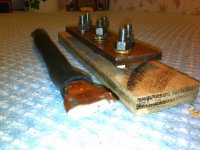
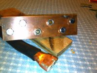
created a positive bus bar for the boat

sdowney717

Well-known member
Joined
Mar 17, 2010
Messages
964
made it from copper sheet, 3 pieces of 1/8 sheet copper soldered together 2 by 7 inches. Each side was individually tinned the whole side then heated together to join.
tapped 6 holes for bolt studs

Then I created a 14 inch wire, used nibco copper pipe reducers for the ends, smashed fit with hammer with copper wire inside and soldered sealed the ends
I covered the wire with 5/8 rubber heater hose.
The copper strands were from an old jumper cable plus some 8 gauge multistrand wire laying around.

made a wood block sealed with polyurethane and also the backside of the copper bus bar.


I needed a distribution expansion point for the inverter wiring as the single stud coming from the 4 way battery switch was insufficient space wise.
I imagine the wire is similar to a 4/0 wire.
I put up some pics to show you.

so now instead of 6 wires coming right off the switch post, the idea is to run that single wire to the bus and hook it all up there. Starters, house wires, inverter positive , raritan lectrasan toilet,
 

Attachments

  • IMG_02261239.jpg
    IMG_02261239.jpg
    70.6 KB · Views: 71
  • IMG_02271240.jpg
    IMG_02271240.jpg
    66 KB · Views: 63
  • IMG_02281238.jpg
    IMG_02281238.jpg
    74.2 KB · Views: 60
  • IMG_02291237.jpg
    IMG_02291237.jpg
    75.1 KB · Views: 58
Last edited:
To avoid these ads, REGISTER NOW!

Alchymist

Well-known member
Joined
Mar 1, 2009
Messages
4,423
Location
Central PA
Did something similar for our 5th wheel - switched distribution for dual batteries and split load. Aluminum block standoffs, hinged one end, and bakelite mounting for the switches.
 

Attachments

  • Bswitch1.jpg
    Bswitch1.jpg
    144.1 KB · Views: 36
  • Bswitch2.jpg
    Bswitch2.jpg
    138.1 KB · Views: 37
  • Bswitch3.jpg
    Bswitch3.jpg
    144 KB · Views: 34

wssix99

Well-known member
Joined
Mar 2, 2011
Messages
5,168
Location
Chicago, IL
This is a good guide you may want to look at for your boat: http://www.uscgboating.org/assets/pdf/downloads/PART1.pdf

For example, I think there is a requirement at the end of the electrical section that requires that you install a fuse/breaker on your wire to the bus bar since its not a part of the cranking circuit.

Have you thought of how you are going to cap/cover the bar when you install it? With different metals on the wire, bolts, and washers, (looks like copper, brass, and nickel) you may also have to take corrosion prevention measures.
 
To avoid these ads, REGISTER NOW!
OP
S

sdowney717

Well-known member
Joined
Mar 17, 2010
Messages
964
yes, plan to grease it and it never gets wet there.

Thinking of a cover either made of plywood over the top or a plastic piece. I painted the wood block black after I put on the polyurethane.

I actually am going to try running the starters from this bar.
This boat built in 1970 has never had a main fuse on the 12 volt feeders.
 

wssix99

Well-known member
Joined
Mar 2, 2011
Messages
5,168
Location
Chicago, IL
I was thinking more of galvanic corrosion. If the hardware is nickel plated, it shouldn't corrode too much in the presence of copper. However; if those washers are certain types of brass, you could have more of an issue. Switching the washers to the same metal as the hardware should get it to last longer for you.
 
OP
S

sdowney717

Well-known member
Joined
Mar 17, 2010
Messages
964
actually all the nuts and washers are stainless.
4 bolts are grade 5, the center 2 are stainless studs, from an old OMC bell housing, one side of stud is coarse thread, the other is fine thread..
was going to use all stainless but the cost was $4 for 4 bolts versus $2 for grade 5 and I dont think that matters much.
I went out to the boat and hooked it up. It works and fits nice.
I simply plan to put some grease coating on the surface and then cover it likely with a piece of HDPE plastic. Likely a strip cut from an old bottle.
The nuts simply keep the pressure on and the copper to copper faces easily carry the current. The buss bars you buy use stainless studs, Nobody sells bronze bolts locally.

My total cost was $4 for bolts, $4 for the copper pipe reducers for the wire ends. I had everything else laying around here.

I drilled out the wood backing to make space for the copper bar bolts sticking off the backside and screwed the bar to the wood with a couple small stainless screws.

I pulled the genset starter wires to use for the inverter. I have a set I took off a 350 Diesel clunker buick to use for starting the gen set. So having extra wires of various lengths I was also able to shorten the positive wire run by a foot for each starter motor and got 1 foot slightly longer wire for the negative return from the inverter which runs straight back to the battery. I originally was going to simply bolt the inverter wire to the engine block and perhaps run a short wire between where I would have bolted the inverter negative to the block and the battery. So the path is shorter.

For some reason all the 12 volt wires are really beefy compared to wires you would find for a starter today on a car. the diesel wires are better than the gas engine starter wires but still not as thick as those on this boat

Inverter is mounted under the galley sink in a large cabinet and away from the engine room.
I re-wrapped all the ends where copper meets rubber wire cover using self vulcanizing rubber tape. That tape works well and seals better than vinyl electric tape.
 
Last edited:
To avoid these ads, REGISTER NOW!
Top Bottom