To avoid these ads, REGISTER NOW!

Critique my compressor modification plan

wolfsburged

Well-known member
Joined
Jan 31, 2011
Messages
128
Location
Cary, NC
I have an 80 gallon vertical compressor, 5HP Kobalt single stage model.

Two things I would like to accomplish:

1. Lower the overall height of the compressor assembly to fit in a corner of my basement with reduced height

2. Install an after cooler between compressor pump and tank

My plan is to build a short table and mount the compressor, motor, belt guard assembly onto the table at a level approximately half height of the tank. This will reduce the overall height of the compressor assembly about 2 ft and allow it to squeeze into the corner I want to put it.

Then between the pump and tank I will have to plumb new piping, and might as well add the after cooler. I would have the after cooler hot side/inlet mounted below the outlet of the pump, and the cool side/outlet of the cooler even lower. Then a Tee fitting down to a drain valve to remove the water, and the other leg going up to the existing tank inlet port at the top of the tank.

Photo for reference:
Aftercooler.JPG


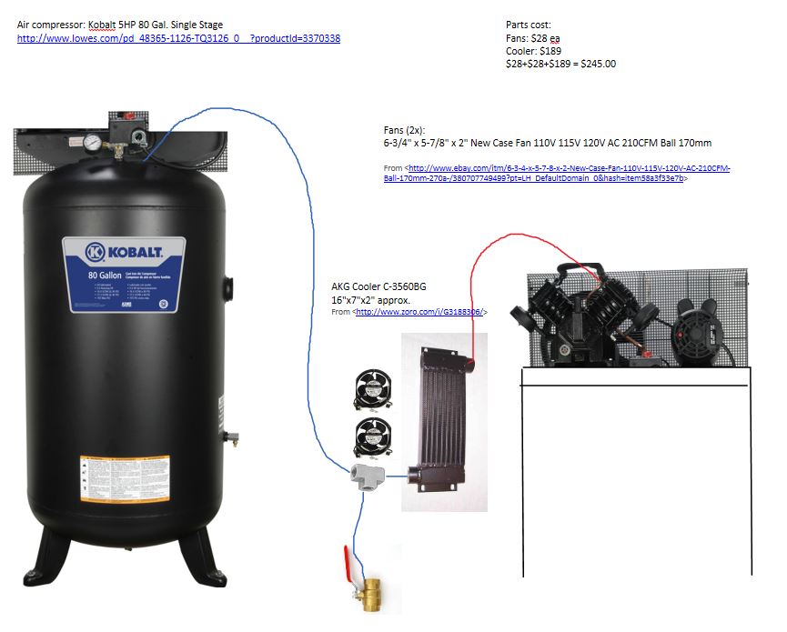
Thinking of this cooler:
Air Cooled Aftercooler, Max HP 15, 60 CFM
Model #C-3560BG
~$188
http://www.zoro.com/i/G3188306/

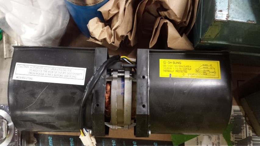
These 120V fans (2x):
6-3/4" x 5-7/8" x 2" New Case Fan 110V 115V 120V AC 210CFM Ball 170mm
http://www.ebay.com/itm/6-3-4-x-5-7...499?pt=LH_DefaultDomain_0&hash=item58a3f33e7b

And misc. copper pipe and fittings to make it all work. Pretty sure existing tubing from compressor outlet to tank inlet is 1/2" stainless tube.

Thoughts/critiques before I try this?

Thanks!
Bill
 
To avoid these ads, REGISTER NOW!

RECox286

Well-known member
Joined
Apr 11, 2012
Messages
1,399
Location
South Joisey (yeah, that is part of the USA)
I have done a very similar setup, using an old refrigeration pump

and pressure tank plumbed to fit underneath the steps to my

cellar. There is no reason why your proposal will not work for you.

Mfg's only build machinery to make it simple to set up and use, so

putting everything together or building separate modules doesn't

necessarily mean anything to the operation of the machine. I see

nothiing wrong with your idea. Send some pics when it's done !

Uncle Bob
 

JRC3

Well-known member
Joined
Jun 30, 2014
Messages
12,481
Location
Southwestern OH
That air cooler looks a lot like a transmission cooler. I wonder what PSI a trans cooler is good for.
 
OP
W

wolfsburged

Well-known member
Joined
Jan 31, 2011
Messages
128
Location
Cary, NC
I would think a trans cooler would work as well, however most have the inlet and outlet on the same side. This has them on opposite corners which should work better for allowing water to drain naturally.

If I could find a cheaper alternative that has the same port configuration and is not too small or restrictive that would be great, especially if it were something I could pull from a heavy duty truck at a junkyard or something.
 

gearhead1

Well-known member
Joined
Oct 14, 2013
Messages
1,935
Location
NC
That air cooler looks a lot like a transmission cooler. I wonder what PSI a trans cooler is good for.

That's the only concern I would have also. Not being a smartass, but the link he posted says it's good for 250 PSI, so no issue there.

It is another component to fail, so I'd recommend to shut the valve off at the tank when you're not using it and kill the power. If it ever breaks, you don't want the compressor sit and run non-stop.

I see no reason it won't work, would be unsafe, or would damage anything.
 

404

Well-known member
Joined
Aug 23, 2014
Messages
3,463
Location
Mass
Very nice picture. Overall I like it a lot. The extra ball valve on the bottom is not going to do much but is not harmful. Be sure to build a plenum between the fan and the after cooler, 1 fan diameter deep is enough. Seal plenum well to cooler and fans. Suggest fans blowing out of plenum and cooler on suction side.

Consider using a centrifugal blower or 2 out of over the range microwave oven. Or the blower (hamster) wheel and motor out of an old AC. The air resistance of the cooler may be higher than best fan operation, where a blower will overcome the resistance better. This concept gets into fan curves which are explained here.


http://www.ebmpapst.us/media/content/downloads_1/support_1/tech_articles/Airflow.pdf
 

1953mercury

Well-known member
Joined
Nov 25, 2012
Messages
701
Location
Steamboat Springs CO
I changed mine from vertical to horizontal so I could put it in my loft area. The same operation would save you floor space, and you could put shelving above it. I cut off the legs and compressor/motor mount and reattached. Mike


CNGsaves

Well-known member
Joined
Sep 26, 2012
Messages
13,233
Location
KS and OK
Looks like good plan since you're separating compressor from tank. Yours will be bit different as you'll want flexible hydraulic line off compressor to short segment of hardline that feeds aftercooler (ie to handle vibration).

+1 for the ball valve shutoff after tank before your air supply hits airline system.

With your aftercooler, you could have a long drip leg with auto drain (instead of ball valve you have shown) so water would be taken out BEFORE it ever got to the tank, then normal drain (manual or auto) at bottom of tank. Good luck.
 

C96

Well-known member
Joined
Nov 30, 2013
Messages
1,251
I changed mine from vertical to horizontal so I could put it in my loft area. The same operation would save you floor space, and you could put shelving above it. I cut off the legs and compressor/motor mount and reattached. Mike


So, this means you’ve done a considerable amount of cutting, grinding and welding on your tank?

Did you also weld-in a new bung for the tank drain now that it’s horizontal, or able to use an existing outlet?

Were you a little concerned about welding on the tank?

Some here on GJ will cut you down for welding a pressure vessel.

From the picture, looks factory.
 
OP
W

wolfsburged

Well-known member
Joined
Jan 31, 2011
Messages
128
Location
Cary, NC
Considered converting the tank to horizontal, but the only ports on the side are currently stacked vertical from each other. I.e. once it becomes horizontal, the outlet port and drain would both be facing straight down which would not be ideal (more water leaving via main outlet!). I don't intend to modify the tank in any way; my proposed layout will take up a little more floor space but the area I'm putting in has a lot of unusable floor space due to the low height, so that is a trade off I'm willing to make.

I do keep a ball valve on the tank outlet so that I can disconnect the tank from the hard piped system for maintenance.

I will consider adding an automatic drain on the drip leg from the cooler. This is a good point, as this will probably fill up quickly relative to my normal tank draining procedure.

Is there a recommendation on a simple and inexpensive auto drain here?

I will look into small blower fans, see if I can scavenge something that will work. I intend to wire the fans so that they run when the pressure switch calls for the motor to run.

Thanks for all the feedback so far!
 

1953mercury

Well-known member
Joined
Nov 25, 2012
Messages
701
Location
Steamboat Springs CO
So, this means you’ve done a considerable amount of cutting, grinding and welding on your tank?

Did you also weld-in a new bung for the tank drain now that it’s horizontal, or able to use an existing outlet?

Were you a little concerned about welding on the tank?

Some here on GJ will cut you down for welding a pressure vessel.

From the picture, looks factory.

I was able to use existing bungs. The welding didn't concern me, the tank is welded in production and I have sufficient faith in my welding skills. Fabrication work took maybe half a day less paint. It has been running just fine for 20 some years. Mike
 
Last edited:

C96

Well-known member
Joined
Nov 30, 2013
Messages
1,251
All I can say is good work Mike! After 20 years… obviously you did fine.

Hell, there have been threads posted about brand new IR compressors with pinholes in the weld of the tank bungs. :wtf:

Again, from the pics it looks like a factory horizontal unit, nice job :beer:
 
To avoid these ads, REGISTER NOW!

OccupantRJ

Well-known member
Joined
May 15, 2009
Messages
11,068
Location
Eastern North Carolina
I had a guy who once worked for me. He was previously a tank welder and showed me his certification. He did not weld for me on this job. He could not even take two-step directions. Dumb as a bag of hammers. Every time I see a factory tank weld, I think about people of his caliber welding them.
 

Jere

Well-known member
Joined
Oct 26, 2011
Messages
708

rsanter

Well-known member
Joined
Dec 22, 2007
Messages
18,514
Location
visalia ca
If,you are going to do that I would go one step further.
Larger commercial systems use two tanks, a wet tank and a dry tank.

I would buy or build a smaller wet tank to feel the compressor directly Into. Then use a water separator between the wet tank and the dry tank which would be your existing tank.

For the wet tank you can use a smaller compressor tank or you can make one with some steel pipe and a few fittings. Take about a 4" pipe that is roughly the height of the original tank. Pipe the compressor into it at about mid height. Feed off the top of the wet tank to go to the dryer and dry tank. Be sre to have a drain valve in the bottom of the wet tank.
The wet tank will give some cooling as well and will even catch most of the compressor oil that passes
 

marinusdees

Well-known member
Joined
Oct 30, 2012
Messages
1,325
Location
Edgewood, Washington
Put a solenoid valve on the drain outfall. Put a solenoid valve inline. 240 or 120 volt coil as you see fit. Feed the solenoid valve current from:
A timer clock, cheap. Activate solenoid and adjust tank drain for minimal flow. Set for 15 minute on intervals every 24 hours.

Or. feed solenoid from compressor on switch.
adjust flow to minimum.

Put a can or jar under drain plumbing. Every time the compressor cycles, it will drain.
 

djb2

Well-known member
Joined
Apr 3, 2010
Messages
639
Location
Redwood forests
I had a guy who once worked for me. He was previously a tank welder and showed me his certification. He did not weld for me on this job. He could not even take two-step directions. Dumb as a bag of hammers. Every time I see a factory tank weld, I think about people of his caliber welding them.

That's exactly the guy I would want welding in a factory. Teach him the one step he needs to do. Don't change the steel, even its thickness. Keep him on that spot in the line until he retires. Hope he doesn't get lost on his drive from home to work.
 
OP
W

wolfsburged

Well-known member
Joined
Jan 31, 2011
Messages
128
Location
Cary, NC
Ordered the AKG cooler and the Amazon auto-drain solenoid tonight.

Still on the fence about the fans. Not sure if the small case fans I found initially will be strong enough, or if I'm over thinking that part. May have to hit the Habitat Restore/Goodwill this weekend and see if I can find something with a blower fan to re-purpose.

Other suggestions on the fans welcome. Would prefer 120V.
 

404

Well-known member
Joined
Aug 23, 2014
Messages
3,463
Location
Mass
I get my blowers on trash day. The case fans will do some good, question is how good do you want it to be. For better good a blower would be better.
 
OP
W

wolfsburged

Well-known member
Joined
Jan 31, 2011
Messages
128
Location
Cary, NC
Not much progress on this other than I had received my aftercooler core.

A buddy saved me this fan from an old microwave. Think it will work well for this? It is about 10"x5" so I would need to make a shroud.

20150512_211045.jpg


In case the sticker is not clear it reads:

OH SUNG (what a brand!)

OBB-1312X1. 120V 60Hz Class A
130/80W 1.1/0.7A CAP .6uF
THERMALLY PROTECTED

The diagram shows:
Black (H) (assuming high speed motor winding)
White (L) (assuming low speed motor winding)
Yellow & Red are shown as what appear to be a normally open contact? Next to the word CAP
Blue appears to be the motor winding neutral

I would assume for my application to simply wire the Black as 120V hot and Blue to 120V neutral. I am not clear on the diagram if the capacitor is built in to the motor and is wired between Black/White and Blue, or if the Yellow and Red are supposed to be connected to an external capacitor with specs as listed on the label?
 
To avoid these ads, REGISTER NOW!
Top Bottom