To avoid these ads, REGISTER NOW!

Custom totes for hand planes

xnology

Well-known member
Joined
Nov 5, 2021
Messages
97
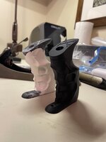
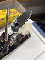
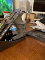
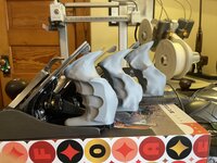
I’ve read a few post here and on other sites about guys with arthritis making totes that help their hands when they are using hand planes. I decided to give it a try. This is my first shot. I intend to carry the designs through and make them in wood when I get to the final fitments.

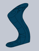
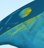
I have a basic pdf of a Lee Valley/Stanley hybrid showing how a section through it and mine differ. I will see if I can get it to upload.
 

Attachments

  • IMG_5051.jpeg
    IMG_5051.jpeg
    533.8 KB · Views: 54
  • IMG_5052.jpeg
    IMG_5052.jpeg
    513.8 KB · Views: 47
  • IMG_5053.jpeg
    IMG_5053.jpeg
    683.2 KB · Views: 41
  • IMG_5055.jpeg
    IMG_5055.jpeg
    523.5 KB · Views: 41
  • IMG_5056.jpeg
    IMG_5056.jpeg
    661.6 KB · Views: 47
To avoid these ads, REGISTER NOW!

RTM

Well-known member
Joined
May 13, 2019
Messages
13,053
Location
SF Bay Area
Other people make them for big or small hands, or just cuz they're bored. Some even make them when the plane comes without them.

One guy used to use modeling clay to get his finger grips right, then carve to match.

Keep going, wanna see these when you're done.
 
OP
X

xnology

Well-known member
Joined
Nov 5, 2021
Messages
97
Other people make them for big or small hands, or just cuz they're bored. Some even make them when the plane comes without them.

One guy used to use modeling clay to get his finger grips right, then carve to match.

Keep going, wanna see these when you're done.

I used clay. It is the only way to get it really close out of the gate - and if you really want it to fit as perfectly as possible.

I need to tune up my #5’s & 6’s and really give this tote a work out.
 
  • Like
Reactions: RTM
OP
X

xnology

Well-known member
Joined
Nov 5, 2021
Messages
97
Don't know if this is going to work.
 

Attachments

  • X-5 TOTE.pdf
    74.3 KB · Views: 14
  • Like
Reactions: RTM
OP
X

xnology

Well-known member
Joined
Nov 5, 2021
Messages
97
On the back of a #6. I’m pretty sure I’m going to end up with two separate 3 and 4 totes.
 

Attachments

  • IMG_5065.jpeg
    IMG_5065.jpeg
    484.1 KB · Views: 40
  • IMG_5062.jpeg
    IMG_5062.jpeg
    532.2 KB · Views: 32
  • IMG_5061.jpeg
    IMG_5061.jpeg
    573.3 KB · Views: 33
OP
X

xnology

Well-known member
Joined
Nov 5, 2021
Messages
97
Can you use clay, get it like you want, do a 3d scan and then output to a 3d print?
Exactly what I did. Had to massage the scan to get it where I want it. Most scanners that don’t cost a jillion are not super accurate, but close enough for a tote for sure!
 
OP
X

xnology

Well-known member
Joined
Nov 5, 2021
Messages
97
I used an air dry clay. It’s air dried in 24 hours of shaping. Sanded and filed and filled the cracks. Then scanned three passes and the mesh massage began!
 
OP
X

xnology

Well-known member
Joined
Nov 5, 2021
Messages
97
The prototype shaped tote with clay applied, filled, sanded and rubbed out.
 

Attachments

  • IMG_5067.jpeg
    IMG_5067.jpeg
    448.7 KB · Views: 33
  • IMG_5066.jpeg
    IMG_5066.jpeg
    503.2 KB · Views: 37
OP
X

xnology

Well-known member
Joined
Nov 5, 2021
Messages
97
So could someone send you a dried hand mold and have you print a custom tote?
In theory yes. I still have to massage the 3D scans quite a bit to make them usable.

When you scan the tote, the holes generally do not scan correctly. They are long and thin and trying to get the tote on the scanning table so the camera sees all the data for the holes is not feasible with what I've got.

I have the model of the tote that the clay is adhered to so I manipulate the scan enough to align the scan and my tote model. This allows me to subtract the model from the scan then I can clean up loose ends from the scan and recombine the model and scan. Then its easy peasy.

So, technically yes. You could send me a tote with a dried clay mold on it. I could scan it and print it.

Also technically no. Without the behind the scenes work, the print wouldn't be very useful. Technology will get there, but for the equipment at my disposal today, it isn't there quite yet.

Maybe someone on the journal has better scanning equipment and software.
 
OP
X

xnology

Well-known member
Joined
Nov 5, 2021
Messages
97
I also did a bunch of sanding and fitting for over an hour to get it right before I scanned it.
 
OP
X

xnology

Well-known member
Joined
Nov 5, 2021
Messages
97
This is what the CAD looked like before printing this afternoon.
 

Attachments

  • image_2025-02-13_220845282.png
    image_2025-02-13_220845282.png
    287.8 KB · Views: 28
OP
X

xnology

Well-known member
Joined
Nov 5, 2021
Messages
97
Here is the last prototype prior to applying clay. I got the size where I wanted it before I applied any custom fitment to it. It is taller and tilted forward more. Then the fingers go farther back at the bottom.
 

Attachments

  • image_2025-02-13_221159349.png
    image_2025-02-13_221159349.png
    40.7 KB · Views: 31
OP
X

xnology

Well-known member
Joined
Nov 5, 2021
Messages
97
I went through 9 3D printed revisions before I printed the above tote. Then I slapped clay on it.

I already have 7 or 8 printed revisions to the basic shape for my #3 and #4 totes. I think my #4 will also be what I put on the #5-1/4.

A lot of work, but 3D is what I do so I enjoy it - immensly when its something I am passionate about.
 

RTM

Well-known member
Joined
May 13, 2019
Messages
13,053
Location
SF Bay Area
When you scan the tote, the holes generally do not scan correctly. They are long and thin and trying to get the tote on the scanning table so the camera sees all the data for the holes is not feasible with what I've got
Can you put hi contrast pins in the top hole or both the holes so it scans the pins instead, and thus assume where the holes are. Know nothing about 3d scanning, so pardon my ignorance.
 
OP
X

xnology

Well-known member
Joined
Nov 5, 2021
Messages
97
Can you put hi contrast pins in the top hole or both the holes so it scans the pins instead, and thus assume where the holes are. Know nothing about 3d scanning, so pardon my ignorance.
Sounds logical, but...

The problem with the scanner that I currently have, as well as those that I have researched, is that it really prefers a uniform - ish object as far as color, sheen and contrast are concerned. I have tried many different techniques and when the object being scanned has geometrically important features, I have not found a way to capture all of these features with enough accuracy for my liking.

I have used it for a number of projects and I always end up putting the fine alignment details in well after I have been tuning up the 3D scanned mesh.

It's never as simple as it should be, but I am sure that is the coming tech of the future - just gotta wait for it.
 
  • Like
Reactions: RTM

Old tool guy

Well-known member
Joined
Apr 13, 2023
Messages
3,156
Once the clay is dry and lightly sanded, could you spray paint all one color to get a uniform sheen and color to scan?
 
To avoid these ads, REGISTER NOW!
OP
X

xnology

Well-known member
Joined
Nov 5, 2021
Messages
97
Once the clay is dry and lightly sanded, could you spray paint all one color to get a uniform sheen and color to scan?
I have painted items and I have other surface treatments that help. But nothing makes it come in as right as you'd want it.
Awesome work. Going to make a copy router to reproduce them in wood?

Are you going to share the step file when you’re done?
I can, but is is literally tailored to my exact hand fitment so unless we are twins, it probably wouldn't do you much good. I can post the raw shape file that I got to before the "squeeze" of clay (the bluish one above). But again, it is tailored to how I thought it felt best. I suppose it could be an excellent jumping off point for someone wanting to do their own.
 
OP
X

xnology

Well-known member
Joined
Nov 5, 2021
Messages
97
Challenges of 3D scanning something as intricate as this tote:

Size matters. The more data you can capture the better the final result will be. Scan 01 is the result of three separate scans aligned together. I have already cleaned off the phantom points that inevitably show up - not parts of the scan. Scan 03 shows how many individual points there are in this model - 4.1 million... The file size for the raw STL mesh is 122.5 MB. This file has to be massaged, smoothed, reduced, and more before it can be usable in CAD software to add the fine bits of geometry. CAD software likes the files to be less than 10% of that files size.

Scan 02 shows a close-up of the edge along the horn. You can see the voids that even after three scans at different angles, the data is incomplete. Scan 05 shows that the smooth surface of the top of the horn has microscopic bumps - artifacts the scan cameras put in as the point clusters are calculated. Also looking down the hole for the main screw, you can see where the software just made stuff up because it couldn't get a good enough view down the shaft hole.
 

Attachments

  • Scan 03.JPG
    Scan 03.JPG
    5.1 KB · Views: 23
  • Scan 05.JPG
    Scan 05.JPG
    30.2 KB · Views: 14
  • Scan 02.JPG
    Scan 02.JPG
    118.8 KB · Views: 14
  • Scan 01.JPG
    Scan 01.JPG
    46.7 KB · Views: 22
OP
X

xnology

Well-known member
Joined
Nov 5, 2021
Messages
97
-What sort of CAD software/program are you using after the scan output? I like a wooden handle too, what a treat to custom fit this to your hands.
I work almost exclusively in Solidworks. It's what I use at work.

There are some mesh software studios that I will also use depending on the project. I usually use these to smooth out the mesh and simplify the scans where possible or practical.
 

RoninB4

Well-known member
Joined
Jul 22, 2020
Messages
3,479
Location
Under My House
I work almost exclusively in Solidworks. It's what I use at work.
-It mostly what I used on contract assignments too, occasional contracts for Pro-E, Catia, etc.
There are some mesh software studios that I will also use depending on the project. I usually use these to smooth out the mesh and simplify the scans where possible or practical.
-Haven't used any of those, it's been predominantly solid modeling. assemblies, and drawings. I get to use surfacing now and then. I like what you're doing here, look forward to seeing further developments.
 

Old tool guy

Well-known member
Joined
Apr 13, 2023
Messages
3,156
Why do you need to model the hole? Or anything more than the top & bottom center points? Seems like you could make a simple jig to drill a hole with a drill press after the rest of the tote is created.

And it’s probably a small amount of data, but why include the “X” on top of the handle?
 
OP
X

xnology

Well-known member
Joined
Nov 5, 2021
Messages
97
Why do you need to model the hole? Or anything more than the top & bottom center points? Seems like you could make a simple jig to drill a hole with a drill press after the rest of the tote is created.

And it’s probably a small amount of data, but why include the “X” on top of the handle?
There will be no easy way to jig these for drilling after because of the complexity of the custom fit. That said, I do have to model the hole so I can fit the3D printed tote on an actual plane body and really test it. If I didn't, have one in the model, I'd have to drill the 3d printed piece and then my accuracy goes out the window.

I will eventually have a jig, but it is going to end up being an exact negative of what I am making - purely because I can. This is going way over the top, but being for myself, I can afford to go there.

The "X" is there simply because the base design tote was version 10. Gotta love the Romans! I left it in because it was easier than filling it in in the model. Nothing special.
 
OP
X

xnology

Well-known member
Joined
Nov 5, 2021
Messages
97
I reconfigured my #4 tote design and took out some spaces where my fingers are on the current shape so there would be voids for the clay to depress into as needed. Applied the clay and squoze the tote. Tomorrow it should be dry and I can fill any cracks and sand and smooth. Then scanning.
 

Attachments

  • IMG_5124.jpeg
    IMG_5124.jpeg
    440.5 KB · Views: 17
  • IMG_5123.jpeg
    IMG_5123.jpeg
    482.9 KB · Views: 19
  • IMG_5122.jpeg
    IMG_5122.jpeg
    469.3 KB · Views: 20
  • IMG_5121.jpeg
    IMG_5121.jpeg
    494.3 KB · Views: 30
Last edited:
OP
X

xnology

Well-known member
Joined
Nov 5, 2021
Messages
97
If this one fits better, I will inevitably redo my #5 too. I applied clay to a full tote design on my #5. I think the voids in my #4 base tote are going to make a significant fitment difference.
 
Last edited:
OP
X

xnology

Well-known member
Joined
Nov 5, 2021
Messages
97
And yes, the wrinkles in the clay mold are the nitrile glove I was wearing.
 

RoninB4

Well-known member
Joined
Jul 22, 2020
Messages
3,479
Location
Under My House
-Looks good, I guess the big question is whether it's better to "lock" your fingers into one position or have no flutes that allows multiple positions. Only prolonged use will tell and everybody used tools differently.
 
OP
X

xnology

Well-known member
Joined
Nov 5, 2021
Messages
97
Could you spray your hand with cooking spray?
I haven't tried that yet! I don't know if there would be any adverse reaction from the clay like uneven drying. But I like your thinking.

I don't mind the wrinkles. They will come off when I sand and smooth the part. The feel of it just gets better and better. I checked this morning and there is a fair amount of shrinkage so I have a few fairly large cracks to fill before I can start sanding.

If by some miracle I can devise a small dremell sized replicator and it all works, this is going to be fantastic.

the big question is whether it's better to "lock" your fingers into one position or have no flutes
It is about the ergonomic fluting, but it is also about the custom shape without. The designs I have come to are taller, steeper or shallower, less broad through the grip, etc. Putting the flutes in increases the comfort at rest and in motion substantially.
 
OP
X

xnology

Well-known member
Joined
Nov 5, 2021
Messages
97
I have pushed the horns up as high as I dare to still leave a clear space for the lateral adjustment levers. On the #3, I am still only going to get three fingers on the tote with the index pointing ahead along the iron's edge. That one, I might be able to leave the horn where it is standard because of this tight geometry underneath.
 
OP
X

xnology

Well-known member
Joined
Nov 5, 2021
Messages
97
Picture 5122 looks like 4 fingers. Or is that a different plane?
That's one of my #4 planes. I know that they share a common tote traditionally, but where I'm going full custom, mine will be different from 3's to 4's.
 
OP
X

xnology

Well-known member
Joined
Nov 5, 2021
Messages
97
This is by far the most comfortable fit on an old Stanley No. 3 I have ever felt. I wasn’t really expecting this big of a difference.
 

Attachments

  • IMG_5147.jpeg
    IMG_5147.jpeg
    608.9 KB · Views: 17
  • IMG_5146.jpeg
    IMG_5146.jpeg
    693.9 KB · Views: 16
  • IMG_5139.jpeg
    IMG_5139.jpeg
    619.8 KB · Views: 15
  • IMG_5145.jpeg
    IMG_5145.jpeg
    675.3 KB · Views: 19
OP
X

xnology

Well-known member
Joined
Nov 5, 2021
Messages
97
3, 4, & 5 ready for testing. So far I am assuming they will help with arthritis and fatigue just because of how different they feel at rest. The #3 has a slice off the finger tips because the clay squeeze was deeper than necessary. After the slice off in 3, all three feel very good in the hand.

The #4 has my index finger almost touching the frog. It has me thinking I might try and push them back 1/4” or so. I don’t think I can push the #3 back far enough to gain the forth finger up top… I do have some room before I start getting too close to the threaded rod and brass nut.

Have a killer Sunday!
 

Attachments

  • IMG_5189.jpeg
    IMG_5189.jpeg
    682.2 KB · Views: 10
To avoid these ads, REGISTER NOW!
Top Bottom